


 Quite often, in pursuit of the Internet in the village, there is a need for an antenna with a high gain, 20 dBi or higher. Almost the only option for such an DIY antenna is the use of a parabolic satellite dish. You only need to replace the standard head of the Ku-band satellite TV with your own exciter. This article brings to your attention an easy-to-make, but very effective broadband universal 3G/4G/Wi-Fi MIMO feed of the dish antenna - WBME at frequencies of 1700..2700 MHz…
The question immediately arises. Is it possible to use any suitable antenna as a feed, preferably more powerful? The answer is no. The dish irradiator is not a separate antenna that simply “summing up” with the dish. They work as a whole and the parameters of the antenna feed depend on the parameters of the dish. The antenna exciter selection criteria are as follows:
 The irradiator should, if possible, uniformly illuminate the entire surface of the dish, or, in other words, have a well-defined width of the major lobe of the radiation pattern. And since the gain of any antenna is related to the width of its major lobe, the optimal value of the feed gain is also strongly defined. It depends on the ratio of the focal length of the dish to its diameter (f / D). If we take an antenna feed with a gain higher than optimal, it will illuminate only the center of the dish with a narrow beam, and dish edges will be in shadow. If less, then with its wide major lobe it will shine beyond the dish edges. In both cases, the efficiency of the whole parabolic antenna (dish + feed) will decrease.
- The major lobe shape of the feed radiation pattern in both the vertical and horizontal planes should be approximately the same. Thus, any sectoral antenna is not suitable as a feed. It will only illuminate a narrow strip on the dish, and most of it will be in shadow.
- The feed should have the lowest possible level of the back and side radiation pattern lobes, since they significantly degrade the parameters of the parabolic antenna.
- It is necessary to take into account the influence of the parabolic dish and the antenna feed on each other. The wave from the reflector passes through the feed and changes its input impedance. As a result, the SWR of the antenna changes. The antenna feed also black out the reflector. To reduce these effects, the offset parabolic antenna is used.
- To do offset antenna, we can’t just take and move the feed somewhere to the side. The offset antenna surface is a cutout from the side surface of a large parabolic virtual reflector, and the feed remains at the focus of this virtual parabola. This gives additional difficulties in the calculations.
- The phase center of the antenna feed should be as a point and placed at the focus of the dish, and not spread in space. More on this below
As you can see, designing an antenna feed for an arbitrarily taken parabolic reflector (for example, a homemade one) is not at all an easy task. But the fact that dishes for satellite TV are standardized (f / D = 0.5..0.6) helps us, otherwise we would have to use not standard Ku-heads, but select a separate one for each dish. The optimal feed gain for such a dish is about 9.5 dBi. The WBME antenna feed is the best for use with such a home satellite dish for 4G internet.
WBME - Wide-Band-Magneto-Electric dipole - was proposed by two Chinese scientists - Kwai-Man Luk from the Hong Kong University and Mingjian Li from the University of Wisconsin-Madison (USA) in 2012-2015. It can be represented as a superposition of two elementary radiators. The first radiator is a half-wave dipole, which is equivalent to an elementary electric dipole. The second radiator is a short-circuited quarter-wave patch, the radiating gap of which is equivalent to an elementary magnetic dipole. Together, the patch and the half-wave dipole form a magneto-electric dipole, which, in turn, is equivalent to the Huygens element with a cardioid-shaped radiation pattern. Let us draw the reader's attention to the fact that the concepts of "magnetic dipole", "electric dipole", "Huygens element" are virtual mathematical abstractions from electrodynamics and antenna theory. "Half-wave dipole", "short-circuited quarter-wave patch", "magnetic-electric dipole" are real antennas that you can feel with your hands. Note that an abstract elementary electric dipole and a real dipole are two completely different entities. However, they are denoted by one word - dipole. This can easily lead to confusion. In fact, abstractions are designed to simplify calculations and understanding the physics of phenomena, but for a practical worker who is used to have to do with real hardware, abstractions are perceived rather hard. And here also with real antennas they are called in one word! Here and to mess in the head is not far. Keep this in mind.
Now let's go directly to the hardware. Our MIMO antenna feed consists of two orthogonal nested magnetoelectric dipoles with a common reflector in the form of a box. Each dipole is excited by the U-shaped probe, which is also a balun.
 The reflector box has dimensions of 116x116x36 mm. Inside it, on stands made of aluminum profile 15x15 mm 34.5 mm high, parts of dipoles 28x28 mm made of aluminum 0.5 mm thick are fixed. In a 7 mm wide slot between the stands there are U-shaped excitation probes made of copper tape 5 mm wide with one end soldered to the central conductor of the connector (there are two of them for MIMO - "port1" and "port2"). The probes must not be in contact with each other. The thickness of the probe strips is not critical - 0.3...0.7 mm. Having drawn diagonals from the corners of the box bottom, we will find the center of the antenna reflector, from which we should begin, making markings.
The feed proposed in this article was calculated by yurik82 for standard materials that can be bought at any building supermarket. The characteristics of the feed and the offset parabolic antenna with a diameter of 0.9 m with this feed can be seen in the images below (click on the image to enlarge):
 |
 |
 |
| Input impedance | VSWR | Gain |
 |
 |
 |
| Back lobe suppression [dB] | Radiation pattern | MIMO ports coupling [dB] |
 |
 |
 |
| Radiation pattern of the dish with the feed | Gain of the dish with the feed | Radiation efficiency [%] |
VSWR within the operating range is not more than 1.7 both at 75-ohm and at 50-ohm load. Therefore, it is reasonable to use the antenna with a cheaper 75-ohm coax. Gain 8-10 dBi. The width of the major lobe at the level of -6 dB is about 60°. The front / back ratio is not worse than 26 dB. Uncoupling between MIMO ports is not worse than 36 dB. When used with a dish with a diameter of 0.9 m, the gain of the parabolic antenna reaches 21..24.5 dBi with a reflector efficiency factor of at least 40%.
The feed should be placed at the focus of the dish, where the Ku-head was. But, since the feed is not small, the question arises. What part of the feed exactly should be placed in the dish focus, because the feed is a rather voluminous object? Usually this issue is not given due importance, however the effectiveness of a parabolic antenna largely depends on this. The phase center of the feed should be placed at the focus of the dish. If we choose a wave front with the same phase within the major lobe of the feed pattern, then it will be like a segment from a virtual sphere. The center of this sphere is the phase center of the antenna. The emitter seems to shine from this point. In a broadband antenna, the phase center is not constant. The frequency changes - the wavelength changes, the position of the phase center changes. The graph below shows the calculated position of the phase center of the feed depending on the frequency, the distance is calculated from the center of the bottom box surface of the feed reflector along the axis of the feed radiation vector: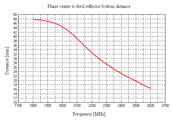 As you can see, the phase center is in the plane of the dipoles at a frequency of about 2160 MHz. At higher frequencies, it is closer to the feed reflector, at lower frequencies, further. When using an antenna in a broadband version, it is allowed to select a phase center for one of the bands. Then, in the remaining bands, the parabolic reflector efficiency will be somewhat less than optimal. In the broadband version with a 0.9 m dish, the optimal average value of 40 mm was chosen. The design of the feed attachment should provide for the possibility of moving it along the axis to accurately set the phase center to the focus and rotation around the axis to adjust the polarization.
Summing up, we underline the advantages of this design:
- The design meets all the criteria for choosing a feed of the offset parabolic antenna, which we listed at the beginning of the article.
- The design is broadband and universal for any microwave data transmission band, both 3G/4G and Wi-Fi.
- Due to its wide bandwidth, the design is highly repeatable and does not require special tuning if carefully made.
- Available and cheap materials are used for the making of the antenna.
Of the lacks, it should be noted that there is no DC short circuit at the antenna input, but since the U-probes is surely hidden from the external environment inside the closed box, the accumulation of static charge on probes is practically excluded, and the antenna does not need additional protection against atmospheric static electricity.
In conclusion, we should note that broadband antennas based on the WBME dipole can be used as budding designs for 5G networks, in which data transmission channels operate in different bands at the same time.
Related links:
- A Wideband Magneto-Electric Dipole Antenna - Lei Ge and Kwai Man Luk, 2012.
- Wideband Magnetoelectric Dipole Antennas With Dual Polarization and Circular Polarization - Mingjian Li and K.M. Luk 2015.
- WBME 1700-2700 MIMO 2x2 (50 or 75 Ohm) - calculating the WBME feed model in HFSS is at the base of this article.
- Probe-fed Dipole over Ground 1700-2700 MHz UWB - simplified (non-MIMO) WBME feed.
- Parabolic Antenna Gain Calculator at 55% efficient factor.




The site has comments on social networks, which have much more opportunities for communication.