We present to your attention the modern BiQuad antenna calculator. The antenna is modeled in HFSS software and optimized for Wi-Fi and 4G bands. The wire diameter corresponds to the standard wire gauge. Without significant changes in the characteristics of the antenna, the closest available one can be used. The shape of the loops is rounded at the bends, which allows you to achieve the widest possible bandwidth and facilitates the making of the antenna. If someone got here in search of a BiQuad antenna calculator for HDTV, then keep in mind that such a “digital” antenna does not require calculation, and it is described in another article. Although, if you just want to calculate a 75-ohm antenna for a specific UHF frequency, then this calculator allows you to do this.
The side pillars are made of metal bolts or studs M2-M8 depending on the diameter of the wire and are attached to the reflector and loops by nuts and washers. Since there are voltage nodes at the attachment points, the so-called zero potential points, currents do not flow through the side pillars. Therefore, metal side pillars can be dielectric, it does not matter. At frequencies above 2 GHz, dielectric side pillars are preferred. Dimensions are given along the central axes of the wire, dimension D - from the wire axis (loops plane) to the reflector surface. Dimension R - rounding radius of the wire. The accuracy of the total length of the wire is important (in this case, the perimeters of each square must be the same), as well as the distances D, dimensions W and H allow for some rounding of dimensions. The radius R is not critical and is approximately the same for all bending points. The gap between the wires at the connection point is as small as possible. The antenna is connected with a 50-ohm or 75-ohm coaxial cable. (SWR < 2). The calculated gain is not less than 10 dBi. The reflector is full-metal, but it is possible to use a mesh reflector, as in the diagram. The parameters of such a reflector can be determined using the online metal mesh reflector calculator. The polarization of the antenna, when positioned as in the diagram, is vertical. For horizontal polarization, rotate the structure 90°..
Schematic representation of the antenna:


© 2015 - 3G-Aerial
Limitations and features of antenna calculations
A calculation similar to this calculator is available in the Cantennator android application available on Google play. You can download it to your mobile device by clicking on the QR code below or by scanning it. Don't forget to rate the app...
For balancing, the supply feeder must be drived through the zero potential point (near one of side pillar) and fixed along one of the loops. The braid is soldered to the shoulder along which the feeder passes, the central conductor to the opposite.
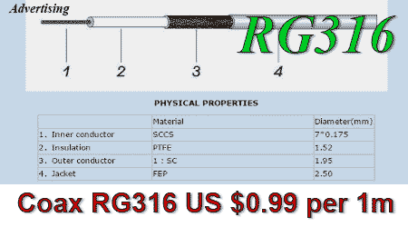
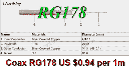
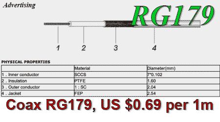
 If at UHF frequencies it is possible to place a main antenna feeder directly along a loop, for example, the common RG6, then on the microwave, this cannot be done. It is necessary to use pigtails made of thin coaxial cable on both sides of the feeder, for example RG178, RG316 for a 50 ohm antenna or RG179 for a 75 ohm antenna. However, to reduce signal attenuation, it is precisely a thick coaxial that is needed as the main antenna feeder. A more kosher way to balance and match the BiQuad microwave antenna is to use a flat three-wire Ruthroff's balun, which not only solves the problems of microwave balancing, but also expands the antenna bandwidth. The design of the BiQuad dual-band antenna at 1800 and 2100 MHz with such a balun will be described on our website.
The wire for loops on low-frequency ranges can be replaced with a metal plate with a width equal to the calculated diameter of the wire. In this case, the length of the path along the center of the plate should be equal to the length of the wire from the calculator.
In the 2100 MHz band (3G UMTS), when tuned to a center frequency of 2045 MHz, the antenna, unlike Double Bi-Quad, has a sufficiently wide bandwidth at SWR < 2 and although it also does not capture both outgoing and incoming channels, however, but if you are not a perfectionist, it may well be used, although in this case it is better to use the improved BiQuad antenna design, optimized specifically for this range. A list of such optimized designs for most ranges is compiled at the end of the article.
. The Wi-Fi range is easily fitted the antenna bandwidth:

Regular users of this calculator have questions. Most of them are explained below in the form of a dialogue:
- -I see that the calculator for BiQuad antenna for Wi-Fi has been updated on your site. I would like to make it and test it in practice, but there were some inaccuracies. Previously, the exact length of the side of the square was indicated in the calculator and it was approximately 30.5 mm. That is, it was necessary to simply take a piece of wire, put marks every 30.5 mm and then bend along them? And if you measure the finished antenna with a caliper, then 30.5 mm should be on the outer edges of the square, on the inner edges or on the center axis of the wire? Now the length of the square side is not indicated at all. There is only the total length of the wire. Why has the calculation changed? For what purpose was this new version made?
- -To begin with, I would like to draw your attention to the fact that the calculator does not "calculate" the antenna, but simply scales its dimensions by frequency. Most wire antennas allow this scaling. But at the base, it should contain a true model calculated in some electromagnetic simulator. This is not the first time we have improved the calculator, the first version did not have a basic model at all, it was based on simple formulas and looked like this calculator. This calculator is incorrect! It simply calculates the side of the square as quarter wavelength and then shortens it by a factor of 0.97. This is a gross technical error. An electric half-wave dipole is indeed shorter than the half wavelength in free space. In our case, the perimeter of the loop, on the contrary, is slightly greater than the wavelength.
- -The second version (previous) was based on the model for the MMANA antenna simulator. The program as well as 4NEC2 is still popular with oldfags. In this app, the wire is represented as a straight, infinitely thin line, so all dimensions are given not along the edges, but along the axis of the wire. The actual diameter of the wire is of course taken into account, but at the secondary additional calculation. Moreover, the program has a number of limitations of the calculation. These limitations are easily satisfied at SW and VHF but it is very difficult to bypass them on the microwave. In particular, MMANA incorrectly takes into account the gap at the connection point. It follows from the MMANA model that the size of this gap affects the input impedance of the antenna. However, since the main limitations of the NEC computing core disregard at the connection point, this conclusion is in fact completely wrong. The program does not model wire bends in principle, only fractures. And since it is impossible to bend a wire, especially a thick one, strictly at 90 degrees, an additional length of wire sums along the bends, which the basic model does not take into account. It is impossible to correctly calculate this length without knowing the actual bending radius. And on the microwave, it is the real total length of the loop with the correct allowance for bends that is very important, and not the length of its side. The resonance of the loop, i.e. the frequency point where the input reactance vanishes, directly depends on this length. Furthermore, a smooth wire bend slightly expands the antenna bandwidth, which is often important. For this reason, it was decided to change the calculator.
- -At present, the standard for calculating microwave antennas is the use of CST STUDIO or ANSYS HFSS software packages. They are devoid of the disadvantages inherent the MMANA or the 4NEC2, so the calculation using these apps is the most accurate. The last version of the calculator is based on the HFSS model and is more accurate than the previous one. To accurately calculate the wire length, the bend radius is set to a fixed value. It is necessary to bend exactly along the guides with a diameter of 14 mm (more precisely, 13.6 mm). But! There is no single, unambiguously "correct" model with "correct" sizes in principle. There are an infinite number of working models with different sizes. Therefore, the question "why are the sizes different there and there?" doesn't make sense. Under the calculator there are links to other working optimized models, including those for Wi-Fi.
- -Thanks a lot for your answer. I got it. So I will make the last version of the antenna. I was thinking of bending the wire in the air on an object with a diameter of 14mm and then attach the finished loops to the reflector on the large-diameter dielectric side columns (for stability). But I don't know how to bend the wire as accurately as possible in this case? Well, the corners, as far as I understood, should all be clearly 90 degrees, but I didn’t succeed the first time.
- -Clearly 90 degrees is not important, this is not even in the model. You just need to keep as close as possible the main dimensions according to the calculator and bend as symmetrically, "beautifully" as possible. The accuracy of the bend radius is also not critical. Only the accuracy of the wire length and the loop/reflector distance is fundamentally important. This affects the input impedance of the antenna. A slight inaccuracy in shape does not lead to any noticeable deviations. You need to measure the total length of the wire, divide it into 8 parts (the approximate length of each part is the length of the sides of the qs1 or qs2 loop according to the drawing). Then bend the wire along 14 mm mandrels at these points. Stretch/compress the resulting loops to fit the dimensions W and H.
P.S: The wire bending algorithm indicated in the last paragraph of the dialogue is quite easy to apply at microwave frequencies. On the UHF, with a thick wire, this is difficult to do. In this case, you can make a template with guides, the coordinates and diameter of which are given by the calculator, and bend the wire along them. But the first step is to first measure the calculated length of the wire. If you have inaccuracies in the template and after bending the wire "the loop ends do not meet", you can correct the profile of the loop so that the required wire length is preserved in any case.
If all the text above is difficult for you to understand, then you can use a simpler BiQuad antenna calculator.
Optimized high-performance designs of BiQuad for several frequency bands with a reflector in the form of a horn-box, which is closed with a radio-transparent plastic cover:
- BiQuad 435 ±5 MHz, 11.4 dBi @ 50Ω
- BiQuad LTE-800 790-890 MHz, 75 Ohm, 11.5-11.7 dBi
- BiQuad GSM-900 890-960 MHz, 50 Ohm, 11.7 dBi
- BiQuad GSM/LTE-1800 1710-1880 MHz, 50 Ohm, 11.7 dBi
- BiQuad UMTS-2100 1920-2170 MHz, 50 Ohm, 11.4-11.8 dBi
- BiQuad 50Ω, WiFi-2440 MHz, 11.4 dBi
- BiQuad LTE-2600 PCB FR4 Dish, 75 Ohm, 10.2-10.7 dBi
- BiQuad + Coax Balun
- High performance UHF HDTV BiQuad antenna;
- #1
- ADW
- #2
- 3G-Aerial admin
The site has comments on social networks, which have much more opportunities for communication.