


 Most designs of microwave antennas for 3G/4G presented on our website can be called amateur non-professional antennas. You can't say the same about the "Ellipse-patch 2x2" antenna. What is the difference between a professional antenna and an amateur one? If we draw a “medical” analogy, then this is like the difference between dietary supplements and certified medicines. Perhaps the first ones help, but they are not recognized by the professional community as drugs. The same situation is with antennas. And just as among dietary supplements you can often find frank fakes, so in the field of antennas there are also myths and fakes. In a professional community the patch antennas are especially popular for Wi-Fi/3G/4G bands. They have a number of undeniable advantages in the microwave range and the "Ellipse-patch 2x2" antenna belongs to this class of antennas.
Why did the professionals choose the patch antenna for the microwave range? What are its benefits? Here is a partial list:
- Possibility of direct connection of a coaxial cable without the use of special baluns;
- The ability to tune both 50 and 75 ohm input impedance by small design modifications;
- Smooth symmetrical radiation pattern with very low side lobes;
- The small depth of the panel layout compared to the BiQuad antenna and other loop antennas (the reflector-patch gap is very small);
- For patches that are symmetrical in rotation by 90° (circle or square), you can get two orthogonal MIMO outputs from one patch with an uncoupling of 23...30 dB, which leads to significant savings on material;
- It is easier to make an antenna stack (phased array antenna) due to the ease of making of the strip transmission lines over a solid ground plane with any necessary characteristic impedance;
- Great suppression of out-of-band radiations, which plays an important role in modern complex electromagnetic environment;
- DC short circuit at the connection point, which is important for protection against atmospheric static;
- Among the disadvantages, one can note the increased weight and high exposure to the wind, however, this does more problems when making of patch antennas for frequencies below the microwave;
Wi-Fi range has a relative bandwidth of only 2%. Unlike the UMTS (LTE) 2100 MHz band that has more than 12% relative bandwidth. As you can see, these are "two big differences". So you need to understand that any, even a professional Wi-Fi antenna, which we scale to a frequency of 2100 MHz, becomes already “amateur”. For this range, you need to design another broadband efficient antenna.
 To create such a broadband antenna, we need to choose an appropriate patch shape and size. To understand how the patch works in the formation of the antenna far field, you can apply the principle of equivalence of the slot dipole to a wire dipole. In this case, with some simplifications, the patch antenna can be represented as some kind of radiating slot loop located at the patch edges above the reflector, with a "magnetic current" matching to the electric current in the equivalent wire loop. The perimeter of such a loop is equal to the perimeter of the patch. To reduce the Q-factor and expand the loop bandwidth, we usually use a thicker wire, which in our case is equivalent to increasing the patch/reflector distance. However, there is a hard limit on this way. When the gap increases above a certain limit (roughly about 7..9 mm at frequencies up to 2700 MHz), unwanted high-order radiation modes appear and the directivity of the antenna drops roundly. Another way to expand the bandwidth is the Disc-Yagi design. Each Yagi element individually is a high-Q resonator, and in general this system is equivalent to a multi-stage band-pass LC filter with a bandwidth wider than that of one LC-circuit. The third way to expand the bandwidth, which we have already used to create the BiQuad antenna for HDTV, is the use of higher-impedance loops (in our case, a patch) with a perimeter of 1.5 or 2 wavelengths. Such loops are less Q-factor and more broadband due to the higher radiation impedance (not to be confused with the input impedance).
 Special studies show that a patch with a perimeter of 2 wavelengths in the form of an ellipse with an aspect ratio of 0.6 (with an eccentricity of 0.8) is most effective. In this case, it is necessary to abandon direct connection to the feeder and the problem of matching such a high-impedance patch appears, which is relatively simply solved using a quarter-wave segment of a transmission stripline. This patch was first proposed by UVE on the lan23 forum in 2010 (here you see the author's photo). Using a stack of a few of these patches in combination with striplines, you can create a broadband efficient high gain antenna for the 2100 MHz band. Several such designs were proposed, with additional technical solutions, links to some of them are collected at the end of the article. Here, for free copy, the design "Ellipse-patch 2x2" by yurik82 is proposed.
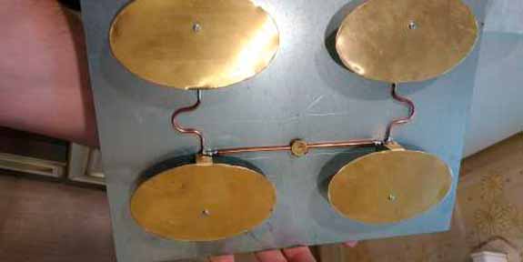
Antenna gain within the working frequency range 15.. 15.7 dBi, SWR does not exceed 1.25. Polarization - vertical. The antenna has two modifications with an input impedance of 50 and 75 ohms. These modifications differ only in the design and location of the connection point. Detailed antenna characteristics with plots of SWR, gain, etc. is available on the author's Live Journal at the first two links at the end of the article. The design of the antenna consists of a solid reflector over which four elliptical patches are attached with plastic bushings and metal bolts. Each patch is excited by a metal tag that is soldered down the middle of the wide edge of the ellipse. All patches are connected in series/parallel by unbalanced wire transmission lines. Detailed instructions for making the antenna:
- Reflector 30x24 cm is made of galvanized or stainless steel. With a thickness of less than 1 mm, it is desirable to reinforce with metal profile crossbars.
- Elliptical patches, 110x66 mm, made of suitable non-ferrous metal 0.5-1 mm thick at a height of 19 mm from the reflector. You can print the template by CorelDraw, AutoCAD or any vector program. Send your templates and we'll publish them here. The holes for attaching the patch with a bolt are offset by 8 mm from the center of the ellipse.
- The step of the phased array is 150 mm horizontally, 120 mm vertically along the centers of the ellipses. Since the holes for mounting bolts are offset by 8 mm from the center, the vertical spacing between the holes for attaching patches to the reflector will be 136 mm.
- The patches are maintained by any plastic wide bushings (for example, from 1/2" PVC pipe) 19 mm high using metal bolts and nuts M3 ... M5 (any suitable). Through these bolts, the ellipses have galvanic contact with the reflector.
- Excitation tag of the patch 12 mm wide and 17 mm high + a small margin for bending and soldering. The length of the tag should be such that, taking into account this bend, the tag does not reach 2 mm from the reflector. The vertical distance of 53.5 mm between the patches is indicated in the diagram, taking into account the tag thickness of 0.25 mm. DIY men who have no shortage of materials can carve the patch and the tag from a single piece of metal sheet.
- The three parts of the phasing transmission line are made of 4mm2 copper wire (Diameter 2.25 mm or 12 AWG#).
- The length of the vertical parts of the phasing line is about 76.8 mm (77 mm) from one tag end to another tag end. The line is bent at 2 points around a tube with a diameter of 14-15 mm. The accuracy of the form is not essential (while keeping the total length), but should be as similar as possible to the drawing with approximately equal gaps of 1.5 centimeters between the straight sections and patches.
- All three wire lines are mounted at a height of 2 mm from the reflector along all length. During installation, it is convenient to place calibration pads of appropriate thickness. Then, at some points, you can drip hot glue to fix it.
- In the 50 ohm version, a circle with a diameter of 12 mm should be cut out of any suitable metal sheet and soldered above a height of approximately 4 mm from the surface of the reflector on the top of the middle of the horizontal phasing TL. The circle is needed to compensate the reactance of the antenna input impedance. At the center of this circle from below, an input port is connected to the phasing line.

- In the 75 Ohm version, the circle is no longer needed. It is necessary to cut a 15x38 mm rectangle (+1 mm margin) from brass sheet (easier to solder) or other metal, working as an impedance transformer. At one edge of the rectangle, cut off the corners to get a narrowing from 15 to 11 mm, remove 2 mm from each edge over a length of 5 mm. Solder the rectangle from above to the center of the horizontal phasing line so that it is 4 mm from the reflector along all length. The distance from the center of the horizontal phasing TL to the input port is 38 mm.

- The 75 ohm feeder is inserted through the reflector using a part of the disassembled F-connector and soldered to the narrow end of the rectangular transformer.
- The whole structure can be hidden in a suitable plastic box. This will avoid the effect of atmospheric conditions. With a margin in the bandwidth, the effect of the box on the characteristics of the antenna can be neglected.
Why is this antenna better than Disc-Yagi? In addition to the fact that it is professional, not amateur, the following advantages can be marked:
- With a comparable consumption of materials, it has an average gain of 5 dB higher. Simply put, it is three times more powerful than the Disc-Yagi. Three times more powerful, buddy!
- Master radio amateurs know how difficult it is to set up a multi-stage band pass filter. And even more so to expect it to work without the fine-tuning. Disc-Yagi, as we noted above, is similar to such a filter. Therefore, it is unlikely that a Disc-Yagi with more than 10 disks will work at all if you do not have an antenna analyzer. High-impedance patches are broadband themselves, so you're more likely to get good results just by carefully repeating the design.
- The "Ellipse-patch 2x2" has a large bandwidth reserve by the SWR < 2 criterion , which means your chances of success increase even more. More simply, in comparison with the Disc-Yagi, the antenna is more repeatable or less sensitive to the ham-handed making.
- It is easier to pick up or make a plastic box for the antenna.
 You say that it is difficult to cut ellipses? Yes, not easy. But, firstly, cutting an even circle is also not quite easy. Secondly, you can strain a little to feel like a professional. In any case, when creating a professional antenna, curve lines are indispensable. However, as the last resort, we can also propose a design in which curvilinear ellipses are replaced by “rectilinear” ones.
Related links:
- Patch Ellipse 2x2, 1920-2170 MHz (UMTS/LTE-2100) 15.1-15.7 dBi @ 50Ω - Original drawings and graphics by yurik82 - 50 ohm variant;
- Patch Ellipse 2x2, 1920-2170 MHz (UMTS/LTE-2100) 15.0-15.7 dBi @ 75Ω - Original drawings and graphics by yurik82 - 75 ohm variant;
- Patch Ellipse 2x2 Rupor, 1920-2170 MHz (UMTS/LTE-2100) 15.9-16.7 dBi @ 50Ω - Option with horn reflector with increased gain from yurik82;
- Patch Ellipse 2x2, 1710-1880 MHz (GSM/LTE-1800) 16.4 dBi @ 50Ω;




Yes, you should.
A bit lost as to why. Suspecting a short at the feedpoint or something.. but any sugggestions or common pifalls to consider?
No. This antenna is optimized only for 2100 MHz band.
To update my previous message:
Turned-out I was using a faulty SMA connector.
It's working brilliantly! I'm having a very stable, high bandwidth connection from a cell-tower several kilometers away. Even through heavy snow and rainfall.
Thanks for the great design!