


 The “Flex” antenna brought to your attention is one of the most effective wire antennas for 3G/4G bands, which can be safely recommended for copy by beginner DIY-ers. With a gain of more than 13 dBi, its bandwidth, according to the SWR < 2 criterion, freely covers any of the currently used bands allocated for 3G/4G mobile networks. The classic Double Bi-Quad is not capable of this, and BiQuad antenna has to be significantly upgraded to make it more broadband. Yes, and BiQuad has much less gain. Why “Flex”? After all, we have almost any wire antenna, a kind of flexible. It just happened. The author of the antenna is com666 (aka the author of the “Extended Batwing” antenna). The antenna was born in discussions and disputes between “practitioners” and “theorists” on the 4PDA forum, and became known precisely under the name “Flex”. Here you can see in a condensed form the already finished results of this discussion with the addition of the online calculator familiar to our site.
The “Flex” antenna, although outwardly similar to a Double BiQuad, has two significant differences from it:
- The loops are not square and in the second level of the antenna array are not the same as in the first one.
- The power supply of the second level of the antenna array does not change phase. In other words, the wires between the levels do not cross.
This antenna has been scaled and optimized by com666 in the 4NEC2 program for mobile Internet bands. As a result, two variants of the antenna were obtained: with triangular and rhombic vertices. This article details the second option, which we recommend for radio amateurs to copy.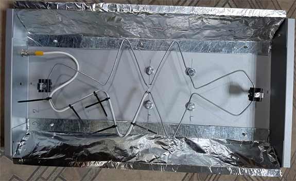
The antenna is placed in a tin box, the dimensions of which can be obtained from the calculator below. It plays the role of a reflector and, in combination, protects the antenna from atmospheric influences. The box is closed with any suitable radio-transparent plastic cover. The active element of the “Flex” is made of copper wire for electrical wiring. It's attached to the bottom of the box on dielectric supports and is powered by a thin pigtail. The pigtail, in order to current balance, is put along one of the sides of the “Flex” and output through the zero potential point located at one of the antenna vertexes. The pigtail can be purchased ready-made with an F-connector on the end, which must be fixed at the bottom of the antenna box. The second connector is simply removed. Choose the length of the pigtail according to the calculator below. It is equal to the total length of the “Flex” wire divided by four plus a margin of several centimeters.
To bend this “Flex”, we recall the school geometry course, mark the abscissa and ordinate axes on the board or piece of plywood and mark the points from the table (h0-h4) around which you need to bend the wire. Since the antenna is symmetrical about both axes, the coordinates of only five of the 18 required points are given (you can set 10 points above the x-axis and bend the half of the antenna). Nails without heads with a diameter of 1 mm are beaten into these points, and thicker ones are beaten into points h0 and h1 (as well as into their mirror counterparts). You can wrap them with electrical tape to achieve the desired diameter of the guide. A pre-straightened wire is stretched around these guides. General drawing of the antenna:
In the drawing, h0…h4 are the guides around which the wire is bent, p0…p4 are the points of bends along the axes of the wire, l1…l5 are the lengths of the segments (including bends). The coordinates of the points h0…h4, p0…p4, the lengths of the segments and the dimensions of the reflector are calculated in the online calculator. The plane of the vibrator is the plane passing through the central axes of the wires. It is allowed to use the wire closest in diameter. For example, if the calculator offers a wire with a diameter of 1.6 mm (2 mm2), then you can take a wire with a diameter of 1.8 mm (2.5 mm2). The antenna has an input impedance of 75 ohms and is designed to work with cheaper 75 ohm feeders. Gain not less than 13 dBi. In the drawing, the antenna has horizontal polarization, in the photo above — vertical. As practice shows, the polarization of the antenna must be selected during installation. We recommend experimenting on place with antenna orientation — 0°, ±45°, 90° relative to vertical position in terms of signal strength and speed.
JavaScript source code:
Copyright ©2019- 3G-Aerial
Limitations and features of antenna calculations
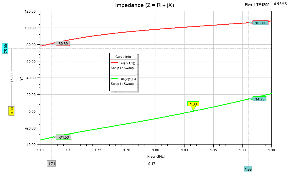
The calculator is based on the “Flex” antenna models in ANSYS HFSS. You can download them as an archive, which contains the original author's 4NEC2 model. The characteristics of the antenna can be viewed in the following images (click on the desired image to enlarge):
 |
 |
 |
 |
| Input impedance | VSWR | Gain dBi | Radiation pattern |
 |
 |
 |
 |
| Input impedance | VSWR | Gain dBi | Radiation pattern |
 The radiation pattern of the “Flex” antenna is sectoral. The major lobe is more narrowed in the vertical plane than in the horizontal one, which makes it easier to tune the antenna to the base station despite its rather high gain. Compared to the “Quados” antenna, the “Flex” has a simpler balancing/matching scheme and allows you to use a cheaper 75-ohm feeder. In addition, Quados has not enough bandwidth at SWR<2 criterion for 3G/4G bands. It should be noted the fundamental difference between the Double BiQuad antenna and the “Flex” antenna. This is a different power supply phasing of the second level of the antenna array. Among specialists, disputes about the advantages and disadvantages of a particular variant do not subside. Let the specialists — “practitioners” and “theorists” — argue. In a dispute, as you know, truth is born. We suggest that DIY-ers simply take advantage of the results of this dispute, say thank you to com666, roll up their sleeves and start bending “Flex” antenna in order to have fast mobile Internet.
Related links:


3g-aerial.biz/en/batwing-antenna-super-wideband-bat-wings-for-3g-4g
3g-aerial.biz/en/wideband-4g-biquad-for-1800-2100-mhz