


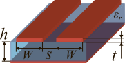
 This calculator computes the parameters of a coupled microstrip with weak edge coupling. Such lines are often used to create microwave bandpass filters and directional couplers. Achieving a coupling coefficient greater than -10 dB with such a line requires a very small spacing, S, which is difficult to get in practice, hence the edge coupling being characterized as weak.
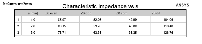
To verify and evaluate the error of this calculator, the characteristic impedances of a series of coupled microstrip on an FR4 substrate with a permittivity of εr = 4.4 at a frequency of f = 2000 MHz were calculated using the ANSYS 2D EXTRACTOR electromagnetic simulator. The calculation results are presented in tabular form:


JavaScript source code:
Copyright ©2026 3G-Aerial
The calculator is based on ©1994-2003 Daniel R. McMahill source codes.
Limitations and features of antenna calculations
Why are there so many several impedances? What are even and odd modes? A separate article is devoted to the answers to these and other questions. A distinctive feature of asymmetric microstrip lines is that the even or odd mode specifies not only the line's characteristic impedance but also its effective permittivity. As a result, the propagation coefficient and electrical length of the line vary in different modes. This problem is solved by adding reactances at the ends of the lines or by coating them with a dielectric layer.
The prototype of this calculator is the calculator at the first link below, which uses the Kirschning & Jansen method. This method takes frequency dispersion into account. The basic calculation formulas can be found at the second link.
References:
- Manfred Kirschning and Rolf Jansen, "Accurate Wide-Range Design Equations for the Frequency-Dependent Characteristic of Parallel Coupled Microstrip Lines", IEEE Transactions on Microwave Theory and Techniques, Vol MTT-32, No 1, January 1984, p83-90. Corrections in MTT-33, No 3, March 1985, p. 288
Related links:
- Coupled Microstrip Analysis/Synthesis Calculator (Copyright © 1994-2009 Daniel R. McMahill);
- Formulas for Impedance of Coupled Microstrip Lines - LibreTexts Engineering;




The site has comments on social networks, which have much more opportunities for communication.