


 Most of the popular antennas presented on our website, such as the BiQuad or Quados antenna, have one significant flaw—not a wide enough bandwidth. It is quite enough only for the Wi-Fi band, but in 3G/4G networks with a common DIY-er who does not have special tuning devices, these antennas will most likely work very badly. In addition, with the rapid development of mobile Internet networks, with the allocation of more and more new bands for this, there is a desire to make an universal broadband antenna for all occasions, and not to constantly remake them or use a set of several antennas and get on yourself nerves constantly switching them back and forth. Is it possible? The improved or expanded Batwing antenna brought to your attention, the authorship of which belongs to the user with the nickname com666 (he is also the author of the “Flex” antenna), is able to satisfy this cherished desire of yours, dear anonymous…
Professional designs
Note that such broadband antennas are already commercially available in beautiful plastic cases. If we look at the insides of such an antenna, then we will most likely find a rather intricately warped figure there, for example, such as in the image. Slightly similar in shape to an old shaving blade, isn't it? You and I can come to the conclusion that in order to manufacture such a “blade” with the required accuracy to tenths of a millimeter, you will need a CNC router equipment. Something tells me that anyone who has the funds to buy such a machine will easily buy a ready-made antenna. Nevertheless, those who are ready to repeat such a design can learn in detail its characteristics in detail here. We will return to the question of why professional antenna designers make such intricate designs at the end of the article. But the presence of smooth lines in this strange antenna quickly discourages even the most reckless antenna enthusiasts from making it. In addition, the result is not very impressive. The bandwidth of this antenna for SWR < 1.6 covers only two adjacent bands: LTE1800+ LTE2100. And our goal is just to help an anonymous make a simple and effective antenna with a minimum of costs, and not in a specialized workshop with a zoo of modern machines. And we are going to get an antenna for the entire high-frequency range: LTE1800+LTE2100+WIFI2400+LTE2600.
 Simple Batwing antenna
To begin with, view a simpler design called Batwing, which means the wing of a bat. The antenna was patented by R.W.Masters in 1945. The antenna is little known to radio amateurs, since it was used mainly as part of transmitting super-turnstile antennas at radio-television centers. But no one bothers to use it as a broadband 4G antenna with the addition of a reflector, which is what com666 did. At 4G bands, it must be taken into account that we have vertical polarization. At the same time, there is absolutely no need to make a antenna from a set of wires, it is made from a galvanized steel sheet, from which two triangles are cut to give the desired shape to our “wing”. Then it is cut in half. Two wire jumpers are soldered along the edges of the cut. The reflector is also a flat square galvanized sheet. The author mounts an antenna in a ready-made case. The radiator mounted in the case is shown at the beginning of this article. The reflector mounted on the cover of the case. Antenna drawing can be seen in the following image:
The antenna has three options of the author's sizes, which are summarized in the table below. The first option is designed for simultaneous operation in the DCS-1800MHz and UMTS-2100MHz bands, the second — simultaneously in the Wi-Fi-2400MHz and LTE-2600MHz bands, and the third — for operation in the entire 1700 – 2700 MHz range.
| Dimension: | Band [MHz] | ||
|---|---|---|---|
| 1800MHz & 2100 MHz | 2400MHz & 2600 MHz | 1700 - 2700 MHz | |
| A × B | 95 × 95 | 95 × 95 | 130 × 130 |
| W | 90 | 60 | 90 |
| L | 72 | 47 | 68 |
| D | 35 | 30 | 35 |
| dw | 22 | 22 | 14 |
| sl | 2 | 2 | 5 |
VSWR within the operating ranges does not exceed 1.5. The gain is about 9 dBi, the front/back ratio is not worse than 11-13 dB. The input impedance is close to 75 ohms, however it works fine with both 50 ohm and 75 ohm feeders. The characteristics of the latest version of Batwing for the 1700-2700 MHz range can be seen in the images below (click to enlarge):
 |
 |
| Input impedance | VSWR |
 |
 |
| Gain dBi | Radiation pattern |
Improved “Extended Batwing” for all bands.
The antenna options presented above have proven themselves in practice. However, no one forbids us to use modern digital technologies and improve the antenna using an electromagnetic simulator ANSYS HFSS, which the author did. As a result, we have extended “bat wings” that are able to cover almost the entire microwave range used for data transmission. Schematic representation of the antenna:
The wings are attached using small dielectric posts in the middle of the triangles. Reflector is a sheet measuring 130×130 mm. Distance wings – reflector 35 mm. The length of each jumper along the edges of the wings is 12.4 mm. The location of the jumpers (to the front or to the side) does not matter. The pigtail is soldered to the wings as in the diagram and then retracted perpendicular to the reflector, then down the reflector.
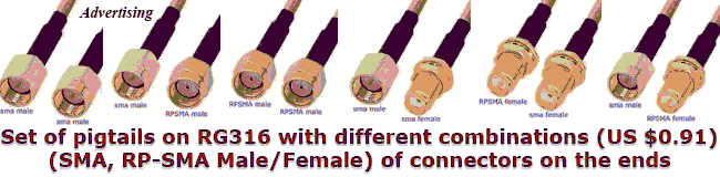
The pigtail with the main feeder can be connected using an adapter – connector. Why such difficulties with the feeder? Read the text below. The reflector and wings are made of any suitable sheet material available to you (for example, galvanized) with a thickness of 0.3-0.8 mm. The antenna can be placed in a suitable plastic case.
The input impedance of the antenna is 75 ohms, and it is designed to work with more affordable and cheap feeders with the same impedance. Antenna bandwidth according to SWR < 1.4 from 1670 to 2730 MHz and includes 4G bands 1800, 2100, 2600 MHz, as well as Wi-Fi 2400 MHz. The antenna gain is about 10 dBi, the front/back ratio is not worse than 17.5 dB. Antenna characteristics:
 |
 |
| Input impedance | VSWR |
 |
 |
| Gain dBi | Radiation pattern |
Note that, like the BiQuad antenna, Batwing is an antenna with a balanced input and a direct connection of the unbalanced cable to the feed point inevitably distorts the radiation pattern due to the lack of a balun. By the HFSS modeling, the author showed that in order to avoid the mutual influence of the feeder and the emitter with an asymmetric power supply of a symmetrical antenna, it is enough to take the feeder away from the radiator perpendicular to the reflector and then along it (or better even behind it) out of the box. In this case, the antenna pattern, according to the author, is no longer distorted, which makes it possible to abandon special balancing schemes. However, by our opinion, the decision to abandon the balun is half-hearted.  To verify this, it is enough to model the antenna with a sufficiently long piece of the feeder that extends beyond the reflector, which the author of the com666 antenna did not do. Then the radiation from the outer side of the feeder and the distortion of the antenna pattern become clearly visible. However, these distortions are so small that the solution proposed by the author can be considered quite workable. Another way
 of balancing—following the example of the BiQuad antenna, path the pigtail along the slot to the point of zero potential (it is located in the center of the jumper) and make a tap from there. This solution makes it possible to achieve a much better balancing, but with vertical polarization it still does not completely solve the problem. It is possible to completely solve the problem of balancing in the microwave only by using patch antennas, for example, a “Double Ellipse-rectangle”. Since, as we have already mentioned, there are zero potential points on the jumpers, it is possible to abandon the four dielectric racks and fasten the antenna to the reflector with metal posts at these “ears”, which was done by the author.
We add another version of the antenna, in which wings can be cut out of one piece of tin with “ears” and the racks for attaching to the reflector. To increase the gain, the side boards are added to the reflector to form a corner horn reflector. The gap in this design is of variable width. In the center at a distance of 8 mm, the slot width is constant and equal to 2 mm, and then it gradually widens to 7 mm towards the edges of the wings. Closing “ears” are built into metal posts 15 mm wide. Characteristics of this antenna:
 |
 |
| Input impedance | VSWR |
 |
 |
| Gain dBi | Radiation pattern |
As we can see, there is no unambiguous “correct” version of Batwing. All options are working, and you have the right to choose the design that suits you. Further improvement of the design will inevitably lead us to the aforementioned “blade”. Why? See below for the text. Here, as a result, we get a universal antenna, for almost all bands, with excellent repeatability, designed to work with a cheap 75-ohm feeder, while all the lines for cutting the antenna web are straight. To miss the working band, you have to try very hard and have very crooked hands. 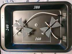 The characteristics of the antenna are much better than BiQuad antenna, and with a comparable gain, it is much better and easier to make. With appropriate scaling, this design can also be used in the UHF range for HDTV. Batwing can also be used for MIMO designs with a common reflector, as shown in the figure.
In conclusion, a few words about why professionals design and manufacture all kinds of the above-mentioned curved “razors”. This is done not so much in order to complicate the copying of such an antenna by a certain “John Doe” and thereby protect himself from a decrease in profit. The reason is that such designs with smooth transitions, including wire ones, are by definition better at microwave frequencies. Why? To understand this, it is not at all necessary to delve into the jungle of differential calculus. It's just that the behavior of an electromagnetic wave and the behavior of the AC current rigidly associated with it on the surface of a conductor are very similar to the movement of a liquid. In fact, this thing was the starting point in the discovery of the electromagnetic wave, since the founder of electrodynamics, J.C. Maxwell, thoroughly studied hydrodynamics, and was the first to draw attention to this similarity. If the liquid moves rapidly along any channel, then in the places of its break this movement slows down, turbulences appear, and the pressure on the channel wall increases. The slowdown in our case is a phase lag, turbulence is parasitic resonances and reflections, pressure is the field strength. Simply put, an antenna with smooth transitions will have a more uniform and wider bandwidth, fewer stray resonances outside of it, fewer side lobes in the radiation pattern i.e., will be of better quality. Well, that's why they are professionals. However, we are not born yesterday too, is it not, dear anonymous?
Related links:
- Batwing antenna - Wikipedia;
- Basic Batwing Properties - L. B. Cebik, W4RNL (SK);
- Detailed Extended Batwing calculation results in HFSS;
- "Flex" antenna - another project from com666;




The site has comments on social networks, which have much more opportunities for communication.