


 We were inspired to write this article by some of the comments on the site, and especially the comments on our Android apps. Many anonymous people believe that it is enough for them to enter any initial data into the calculator and they will get a ready-made antenna at the output. And when they get, for example, a wire diameter of 60 mm at the output, then there is no limit to the indignation. The fact is that calculators are not universal tools, they have certain limitations in use. To understand how to use the calculators correctly, you first need to understand how antennas are generally calculated…
First of all, it should be noted that traditional methods for calculating electrical circuits with simple formulas, such as Ohm's law, are not suitable for calculating antennas. Therefore, it is pointless to google for "Yagi-Uda antenna design equations". There is simply no such equations. When calculating, it is necessary to take into account that the dimensions of the antenna are respective the wavelength, as well as the intense process electromagnetic energy radiation into space. These two cases significantly complicate the theory and calculation methods, since in order to determine the configuration of the electromagnetic field, it is necessary to know the nature of the currents distribution in the antenna, which, in turn, is affected by the radiation field itself. Here is such a vicious circle guys! As a result, we are dealing with a hard mathematic: And this is a fairly simple example from theory, the reality is much harsher. The matter is that the theory and calculation methods were constantly becoming more complicated with the development of radio engineering.
- At the first stage after the invention of radio, ultra-long and long waves with a wavelength measured in kilometers were used. At that, the dimensions of the antennas were much smaller than the wavelength, and the theory of electrical circuits was quite suitable for their calculation. Only a few new concepts have been added, such as radiation resistance, antenna efficiency. Such antennas can be called “point antennas” for convenience. They can be calculated with good accuracy simply as a set of lumped elements - inductance, capacitance, resistance.
- In the mid-20s of the last century, active usage of medium and short waves began. The use of antennas consisting of dipoles, the lengths of which are comparable to the wavelength, has begun. Such antennas can be conditionally called "linear antennas". For this class of antennas, the development of a theory based on the RF transmission lines theory and the theory of radiation of a currents linear combination was required.
- In the second half of the 20th century, the microwave range began to be actively opened up, when all three space dimensions of an antenna are comparable to the wavelength. We will conditionally call such antennas “volumetric antennas”. At the same time, the theory moved to an even more hard mathematics. The calculation is the solution the vector wave equations of the electromagnetic field in a complex form under complex initial and boundary conditions. Moreover, the solution of such equations analytically is most often impossible. It is necessary to apply numerical mathematical methods with iteration. Luckily, the digital revolution has made this task much easier. Programs have appeared to automate these routine complex calculations.
Among radio amateurs, the most popular free programs based on the NEC core are MMANA and 4NEC2. These programs work with antennas represented as a set of infinitely thin straight wires. Wires are programmatically divided into segments, within which the current density is considered constant. The real thickness of the wire is taken into account by a separate algorithm, however, such a simplification leads to some limitations in the calculations, which many people forget about:
- Wire diameter should not exceed 0.02λ;
- The segment length must be less than 0.1λ;
- The segment length must be less than the distance between the nearest wires;
- The segment length must be greater than the wire diameter;
This is an incomplete list, but from it it is clear that in the UHF, and even more so in the microwave range, it is not always possible to fulfill all these requirements. In other words, programs on the NEC core work well with “linear antennas”, and the developer must understand what he is doing and carefully monitor the correctness of the model.
We will analyze another important feature of antenna development using the example of the BiQuad antenna. In principle, the loops of this antenna can be bent in absolutely any way, like squares or rhombuses with equal sides or like rectangles with unequal sides. In other words, there are an infinite number of options for the shape of the antenna, and any of them can be matched with the feeder at the working frequency. If we assume that the loops must be symmetrical and identical, then the number of degrees of freedom according which the loop can be bent can be reduced to three.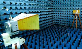 Yagi-Uda has two orders of magnitude more such degrees of freedom. Which option to choose for the assigned characteristics of the antenna? What is the most optimal? These are very difficult questions and earlier, in the pre-digital era, they were solved by careful, lengthy experiments with complex, expensive measurements in a special echo-less chamber, as on the figure. Moreover, finding such an optimal design option was not always successful and was considered a great hit. Such an antenna was usually given the name of the author of this variant, just as comets are given the name of their discoverer. Now enumeration of options and the choice of the optimal one can be entrusted to the computer. An example is N. Mladenov's python script. Guys, it takes hundreds of hours of computer time to find the optimal antenna shape using such a script. And at that you are looking for some "antenna design equations"
In the professional community of microwave antenna developers, the use of CST STUDIO or ANSYS HFSS software packages is currently considered the standard. These apps are already devoid of the shortages inherent in the NEC core, because, simply speaking, instead of a “line”, they work with a “plane” and the models in these apps are more realistic. In addition, they take into account the influence of dielectrics and other materials, which is already critically important for microwaves range. They are more demanding on computer resources, but they also cannot work according to the principle “press a button - get an answer”. The developer must have a solid theoretical background in order to achieve the desired result.
 As you can see, all professional programs require the user to be “on you” with electrodynamics and antenna theory. Knowing the theory, he himself must create a realistic model of the antenna, check it for the absence of errors and blunders. The program only helps to calculate and optimize the characteristics of the antenna. There is no “pressed a button - got an answer”! I’m already sure that the question has come in your head, dear anonymous: “Well, if everything is so complicated, how do your calculators work on the site and in android applications, are they fake?” And experts in general will unequivocally and without looking say that any “calculators” are fake. But it's not. Most of our calculators are based on already calculated computer models and are based on the principle of scaling size by frequency. Most "linear" wire antennas allow this operation over a wide range of frequencies. In this case, all spatial dimensions change, including the diameter of the wire. The MMANA and 4NEC2 programs even have corresponding menu options. Limitations come when you get "inconvenient" sizes, such as the mentioned wire diameter of 60 mm. In this case, another model is obviously needed, with other sizes, and the calculator is not useful. Of course, we are not able to recalculate new models in simulators for all your Wish-list, so the questions: "What if I take a different diameter (or shape) of the wire?", we leave unanswered. We only draw your attention to the fact that replacing a wire or sheet metal with PCB material without recalculation in the simulator is completely unacceptable. Some antennas, such as Wi-Fi “gun”, have non-scalable elements and allow small scaling, no more than ± 30% of the frequency at which the model was calculated (in this case, 2400 MHz). Recalculation further in frequency does not guarantee success. Some calculators, such as the Yagi-Uda DL6WU Antenna Calculator, use proven methods dating back to the pre-digital era, but are also based on the principle of scaling.
In any case, you must understand what you are doing. The principle “pressed a button - got a like” is not our principle. Recalculating the microwave antenna on SW, you really get a fake. One of the anonymous, choosing the dimensions, hard tried to calculate a 50 ohm folded dipole for 27 MHz. Having got nonsense, he was indignant for a long time in the comments. And the folded dipole is, after all, the basis of the antenna theory. We cannot set protection on our calculators from such "foremasters". Therefore, delve into the materiel, guys. If you do not want, than that not not our fault...


The site has comments on social networks, which have much more opportunities for communication.