



In this article, dear reader, let's examine the main parameters that characterize antennas, so that you can, as they say, be in the know.
First of all, it's essential to understand that any antenna possesses the property of reciprocity. This means that it can both receive and transmit radio waves, and its characteristics remain unchanged in either mode. The characteristics of an antenna can be determined both in transmission and reception modes. Moreover, any characteristic of an antenna will be valid for both modes.
- Antenna Radiation Pattern. A 3D plot normalized to the gain relative to an isotropic radiator, characterizing the directional properties of the antenna. The plot is typically displayed in a spherical coordinate system. The graph shows the antenna gain as a function of the angle of arrival of an electromagnetic field of uniform intensity incident on the antenna. The maximum value corresponds to the reference point of the azimuthal angle φ = 0°. The zenith direction is taken as the zero value of the zenith angle θ. It's important not to confuse the elevation angle β, familiar to all antenna installers, with the zenith angle. β = 90° - θ. The point is that if we disregard the influence of the ground, which is almost always valid at microwave frequencies, the antenna parameters are usually calculated at zero elevation angle, that is, when the main lobe is directed toward the horizon. This unwritten rule doesn't always have to be followed. For example, for satellite communication antennas, it's more convenient when the main lobe is directed toward the zenith.
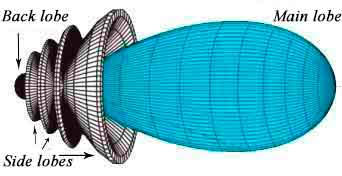 Typically, the 3D radiation pattern plot is symmetrical, which allows us to limit ourselves to two cross-sections in the horizontal and vertical planes. The main lobe of the radiation pattern has the maximum value; in addition to it, a real antenna always has side lobes and a back lobe with much smaller magnitudes. An important parameter is the beamwidth (HPBW - Half Power Beam Width). This is the width of the angular sector whose boundaries are the points at which the received power level drops by half (-3dB), and the field strength, correspondingly, to 70.7% of the maximum value.
 The second important parameter of the radiation pattern is the front-to-back ratio (F/B) or the back lobe suppression level of the radiation pattern. It equals the ratio of the field strength in the forward and backward directions, or the difference in decibel levels between the forward and back lobes. In the above graph, F/B = 11 dB.
- Directivity [D]. The ratio of the power received by this antenna to the power that would be received by an isotropic radiator — an ideal lossless antenna with a spherical radiation pattern. The dependence of directivity on angular coordinates replicates the spatial radiation pattern of the antenna and has its maximum value in the direction of the main lobe. Most often, the term directivity refers specifically to this maximum value.
- Antenna Gain [G]. The product of the maximum directivity and the antenna efficiency. Antenna gain is conventionally expressed in decibel form. Moreover, to avoid confusion, the units dBi or dBd should be used. The narrower the main lobe, the higher the gain. The beamwidth of the radiation pattern and the antenna gain are related by the following approximate formula:
 where αV and αH are the beamwidths in the vertical and horizontal planes, measured in degrees. G is the gain as a ratio, g is the gain in dBi. The formula is valid for antennas with efficiency ≧ 0.8 and when the level of the back and side lobes is 20 or more decibels below the level of the main lobe. On many antenna gain plots calculated in ANSYS HFSS, in addition to "Gain" itself, there is a "Realized Gain" curve. This is the antenna gain that takes into account mismatch losses.
- Radiation Resistance and Loss Resistance, Efficiency. The ratio of the power radiated by the antenna to the square of the maximum current in it is called the radiation resistance. This resistance does not physically exist in the usual sense we understand. It's simply a convenient characteristic of the antenna, whereas the loss resistance has a quite real basis. It characterizes thermal energy losses in conductors, dielectrics, in the ground, and in objects surrounding the antenna. This is the ratio of the power of these losses to the square of the maximum current in the antenna. The higher the antenna's radiation resistance compared to the loss resistance, the higher its efficiency.
- Antenna Input Impedance. As the name suggests, this is the impedance of the antenna measured at its input. In general, it consists of the sum of active and reactive components: Z = Ra + jXa. Many people confuse the active component of the input impedance — the antenna input resistance Ra — with the radiation resistance. They coincide only if the current maximum in the antenna occurs at its input terminals (for example, in a half-wave dipole), and even then only if losses are neglected. In general, these are two very different things. Additionally, there is such a concept as the characteristic impedance of the antenna. It was introduced at the beginning of the last century during the era of linear wire antennas, when transmission line theory was used to explain their operation and perform calculations. With the advent of multi-element and volumetric antennas, this concept lost its relevance and is now typically not used as an antenna parameter. It is also often confused with the antenna input resistance. However, these are not just two different things, but very different things indeed.
- Effective Aperture Area of the Antenna. The area perpendicular to the Poynting vector from which the electromagnetic wave energy is collected. In the case of aperture antennas (horn, reflector), this area nearly coincides with the actual aperture area (reflector). In the case of a single half-wave dipole, this area represents an imaginary ellipse with dimensions of 3λ/4 and λ/4.
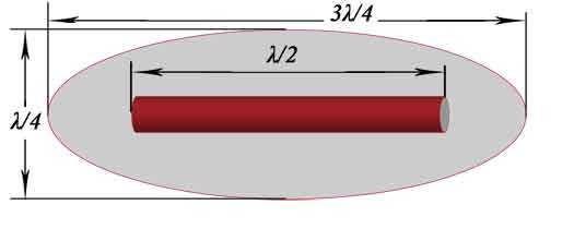 The effective aperture area increases with increasing antenna gain, so the dimensions of the ellipse around a dipole that is part of a Yagi-Uda antenna are significantly larger. When designing an antenna array, it's important to position adjacent antennas in the stack so that their apertures do not overlap each other. The effective aperture area and the directivity of the antenna are related by the following expression:
 where λ is the wavelength, D is the directivity. From the formula, it can be seen that of two antennas with the same directivity, the higher-frequency antenna has a smaller effective area.
- Frequency Range and Bandwidth — the operating frequency range within which the antenna meets the specified electrical and energy parameters, and the difference between the maximum and minimum frequencies of this range, respectively. These can be determined using criteria such as maximum acceptable VSWR, gain, and other antenna parameters. However, the bandwidth determined by one criterion may not coincide with the bandwidth determined by another. This should be kept in mind.
- Antenna Polarization — characterizes the orientation of the plane of the E vector (electric field) relative to the ground. It can be linear, which is divided into vertical, horizontal, and combined. It can also be circular or elliptical.
This is far from a complete list of the main parameters that characterize antennas; for example, in microwave antenna theory, the S-parameters of the antenna play a significant role. It's important to understand that antenna gain is determined by its property of directing the electromagnetic field energy flow in the direction we need. Similar to how a spotlight works. At the same time, there is no increase in the amount of this energy itself in the antenna.
Literature on the topic:
- John D. Kraus - "Antennas";
- Constantine A. Balanis - "Antenna Theory: Analysis and Design";
- Warren L. Stutzman, Gary A. Thiele - "Antenna Theory and Design";




The site has comments on social networks, which have much more opportunities for communication.