


Custom Google Search
Antenna Wi-Fi, 3G, 4G - do it yourself
Moxon Antenna Calculator with Model Export
- Details
- Hits: 13972
 The Moxon rectangle (also called Moxon antenna) is a compact, two-element directive antenna derived from the VK2ABQ square, developed by Les Moxon (G6XN). It's popular among amateur radio operators for its simplicity, low profile, and good performance. The Moxon rectangle consists of two parallel dipole elements bent into a rectangular shape with coupled tips facing each other:
- Driven element — the fed half, forming the top two sides of the rectangle
- Reflector element — the parasitic half, forming the bottom two sides
- Both elements have their ends folded toward each other, leaving a small gap in the center
The shape looks like two "C" or "U" shapes facing each other, forming an almost-closed rectangle.
DIY Yagi-Uda 2.4GHz Wi-Fi Antenna
- Details
- Hits: 8224
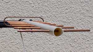 A few years back, video blogger KREOSAN generated massive hype around his "Wi-Fi gun." Many people concluded that all it took was a marker, pliers, and scissors to slap together any microwave antenna without much effort or understanding. They'd then post it on their video blog, hoping it might go viral and turn a profit. What's worse, even failed attempts riddled with glaring technical errors get uploaded to video hosting platforms, leading inexperienced viewers to draw similarly flawed conclusions. In this article, we'll break down these mistakes using one of the most popular antennas as an example: the Yagi-Uda. We'll examine a design for the 2400 MHz Wi-Fi band and analyze how seemingly minor assembly details—ones that appear insignificant at first glance—can cause the antenna to perform abysmally or fail completely.
Yagi antenna elements boom correction calculator with export in ANSYS HFSS
- Details
- Hits: 4784
 MMANA or 4NEC2 users will find this calculator useful. It allows for quick recalculation of optimized antenna dimensions obtained from the model, taking into account boom correction using the DL2KQ formulas. Element lengths can be manually entered, with each value on a new line. You can also select and then load a *.maa or *.nec file; the script will do this automatically. This assumes a simplified model with a linear dipole. The script checks for compliance with this constraint, and inappropriate models will not be loaded. In the results, elements are numbered as they are numbered in the MMANA wire table, and for the NEC file, according to the tag values in the GW cards. Arrays of corrected data are also output, which may be useful for other modelers. The results of recalculating MMANA or 4NEC2 models can be saved as a VBScript for loading and automatically creating a 3D antenna model in ANSYS HFSS.
5/8-wavelength GP vertical antenna calculator
- Details
- Hits: 12940
 Very often, an anonym who came to this site based on search results like “how to calculate a super-duper antenna?” not only don't have the necessary basic knowledge of antennas, but also don't want to pass time reading at least the description of the calculator. As a result, the path ends with questions and anger in the comments. The “five-eighth” antenna is a rather specific antenna, and even surrounded by a number of myths. Therefore, our calculator, firstly, can only be used for rough estimations as a basis for creating a model and further optimization in electromagnetic simulators. And secondly, you should also think about the reasonability of making this antenna. Why so? More details under the cut….
4G LTE MIMO DIY antenna for 700-800-850-900 MHz bands
- Details
- Hits: 7931
 Quickly developing 4G networks require new frequency resources and have long appeared on UHF, from 5th to 20th LTE bands, depending on the region. This requires the development of simple and efficient antennas for these bands. In addition, the presence of MIMO has already become the standard for 4G networks and the manufacture of a SISO antenna for the fourth generation network is completely irrelevant at the moment. To support this technology, we need two antennas. However, if we use a symmetrical patch, then we can combine these two antennas in one, thereby significantly saving on “iron”. This, along with other advantages of the patch -antennas, have determined the choice of this design…
Impedance matching calculator, VSWR and Return loss
- Details
- Hits: 5165
 The impedance at the input end of a transmission line, if it's loaded with a complex impedance at the output, which is most often the case in antenna designing, is also a complex value. This calculator allows you to calculate the input impedance of a transmission line, as well as the VSWR, return loss, and mismatch loss at the input point. It's assumed that the source impedance is also complex. In addition, the calculation takes into account the effect of signal attenuation in the transmission line. Previously, such hard calculations could only be done using the Smith chart.
Antenna “Flex” for 3G/4G & Wi-Fi — high performance alternate for “Double BiQuad”
- Details
- Hits: 8567
 The “Flex” antenna brought to your attention is one of the most effective wire antennas for 3G/4G bands, which can be safely recommended for copy by beginner DIY-ers. With a gain of more than 13 dBi, its bandwidth, according to the SWR < 2 criterion, freely covers any of the currently used bands allocated for 3G/4G mobile networks. The classic Double Bi-Quad is not capable of this, and BiQuad antenna has to be significantly upgraded to make it more broadband. Yes, and BiQuad has much less gain. Why “Flex”? After all, we have almost any wire antenna, a kind of flexible. It just happened. The author of the antenna is com666 (aka the author of the “Extended Batwing” antenna). The antenna was born in discussions and disputes between “practitioners” and “theorists” on the 4PDA forum, and became known precisely under the name “Flex”. Here you can see in a condensed form the already finished results of this discussion with the addition of the online calculator familiar to our site.
Advertising on the website

Download our Cantennator app for antenna calculation from GooglePlay
Scan QR-code, if you are here on desktop, or tap it, if you are here on phone:


Follow the site news on Twitter.
Scan QR-code, if you are here on desktop, or tap it, if you are here on phone:

Read more …