


 To effectively reflect an electromagnetic wave, it is not necessary to use solid metal reflectors. It is enough to use a grid of wires. In addition to saving metal, such a reflector has a much lower windage compared to a solid mirror. Part of the energy seeps through the grid. This calculator allows you to calculate the size of the cells and the loss of electromagnetic energy for leakage.
Javascript source code:
© 2016-2023 3G-Aerial
Limitations and features of antenna calculation
The transmittance p shows the percentage of energy that has gone beyond the reflector. Given the allowable level of leakage loss p and the diameter of the grid wire d, we can find the minimum size of the reflector cell b. It is enough to maintain the distance b between the wires of the grid parallel to the electric field vector E. I.e. with vertical polarization—between vertical wires.
For a perforated reflector, a very small hole diameter corresponds to a very small mesh, and leakage loss can be less than the set allowable value. At the same time, a hole diameter greater than 0.4λ is unacceptable for correct calculation.
For the grid reflector the calculation is by the following formula (p in absolute terms, i.e. for 1% p=0.01):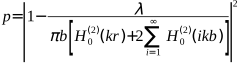
H (2)0 (ikb), Н(2)0 (kr) – cylindrical Bessel functions of the 3rd kind (Hankel functions), k = 2π/λ – angular wavenumber for free space, λ – wavelength, r=d/2 – wire radius.
For the perforated reflector the calculation is by the following formula: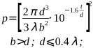 d – perforation hole diameter, b – perforation pitch, t – reflector sheet thickness, λ – wavelength.




The site has comments on social networks, which have much more opportunities for communication.