


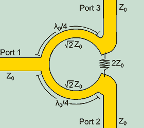
 This device, invented by American engineer E. J. Wilkinson in 1960, can be used as an effective power combiner or divider. It features good isolation of ports from each other, low losses, and is easy for radio-amateur to make himself. Two pieces of coaxial cable and a resistor are enough. To explain the principle of its operation and calculate the characteristics using S-parameters, the Even/Odd mode analysis method is used. We will not go deep into the theory here, it is available at the links at the end of this page. After all, you came here only for the overall result, right, dear anonymous?
The inventor's original idea was that the device could be used as a divider from one input to several outputs, or as a combiner from several inputs to one output. But most often, it is used as a divider/combiner for two. In this case, it is simplified to the view in the image in the article header. Such dividers are frequently cascaded in the form of a tree. In this case, the signal is divided from one input to 2/4/8, etc. number of outputs. In addition, with a slight complication of the circuit, it becomes possible to split the power unequally between the output ports.
The calculator allows you to calculate the characteristic impedance and the length of a quarter-wave section of coaxial cable for a multiway Wilkinson combiner/divider with an optional number of ports at the output/input:
JavaScript source code: Copyright ©2025 3G-Aerial
At wavelengths greater than a meter, coaxial waveguide length are quite large. In this case, the quarterwave section can be replaced by an equivalent P-section low-pass filter of lumped elements. The “characteristic impedance” of such a circuit should be equal to the characteristic impedance of the quarterwave coax-line section.
JavaScript source code: Copyright ©2025 3G-Aerial
The calculation operates by the following formulas: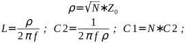
The bandwidth in terms of VSWR is not worse than that of any transformer or divider on quarterwave sections of an RF transmission line. The isolation between ports is more than 30 dB, thermal losses are fractions of a decibel. This is a significant advantage of such a divider in comparison with a resistive one. Unlike quadrature dividers, all outputs in the Wilkinson divider are in-phase.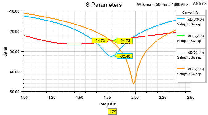 Related links:
- Wilkinson Divider Even and Odd Mode Analysis [PDF];
- Unequal-split Wilkinson Power Divider Calculator;
- Wilkinson Power Splitters - microwaves101.com;




The site has comments on social networks, which have much more opportunities for communication.