


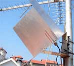
 Considering a corner reflector antenna, you and I, dear anonymous, noted that this antenna, despite its simplicity, has one significant drawback—“high iron spending per 1dB of gain”. The dish reflector antenna is the most efficient in this parameter, but making a parabolic mirror with your own hands is a rather difficult task. However, there is an “intermediate” option with a reflector in the form of a 3D corner. Although its efficiency is less than that of a parabolic reflector, it is much higher than that of a corner reflector antenna. Let's take a closer look at this antenna…
 For the first time, the design of such an antenna was proposed in 1974 by the Japanese Naoki Inagaki. In 2007, this antenna was modeled in the 4NEC2 program and tested in a Wi-Fi network by Dragoslav Dobričić (YU1AW), a radio amateur who is well known to us for the design of Amos and Quados antennas. The antenna is a 3D-corner reflector, on one of the faces of which there is an active element in the form of a pin 3λ/4 long and next to it is a passive element designed to match the antenna with a 50-ohm drop feeder. The antenna radiates along the bisector of the 3D angle, so when installed it should be tilted 45° so that the bisector is directed towards the signal source.
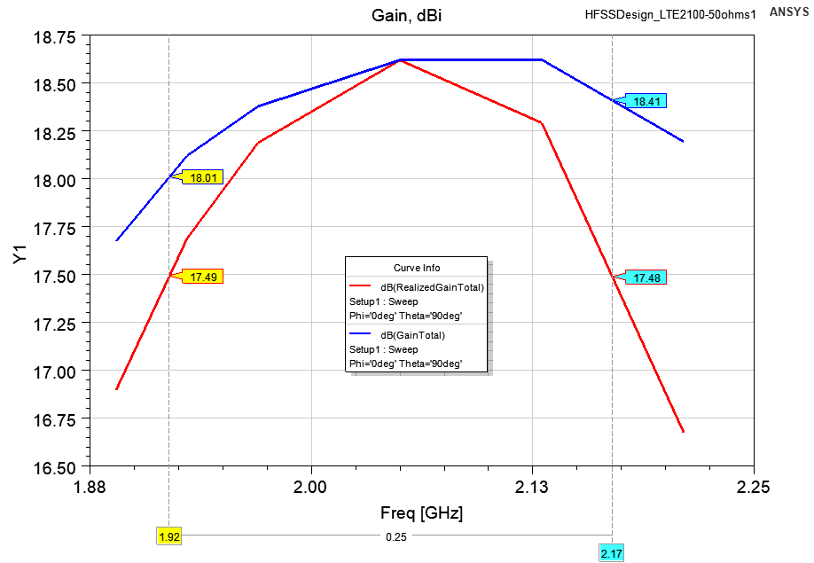
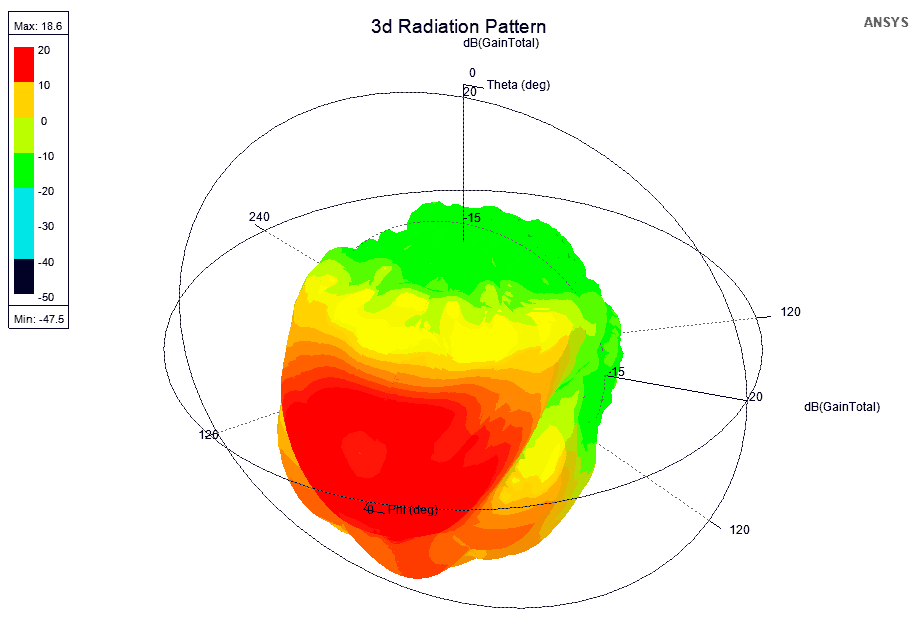
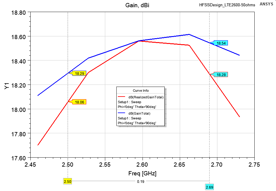
The input impedance of the antenna is 50 ohms in the presence of a passive element, or about 75 ohms—in its absence, the calculated gain is about 18 dBi. Back lobe rejection is no worse than 25dB. Polarization is vertical. Schematic representation of the cutting of the antenna:
JavaScript source code:
Copyright ©2016 - 3G-Aerial
Limitations and features of antenna calculations
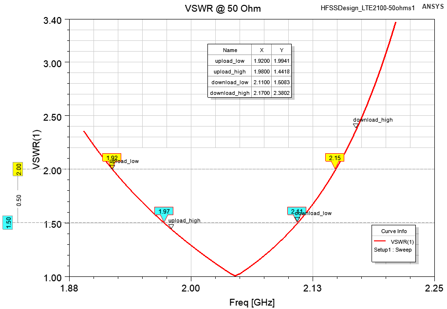
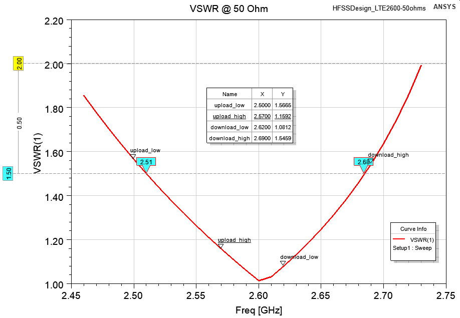
The antenna was modeled in the ANSYS HFSS simulator. How this simulator differs from 4NEC2 and how antennas are calculated in the digital age can be viewed here, and the antenna model can be downloaded from this link. According to the calculation results, the antenna is optimized and the design dimensions are slightly different from the author's version. The results of calculation for two LTE bands can be seen in the following images (click on the one you need to enlarge):
 |
 |
 |
| VSWR | Gain dBi | Radiation pattern |
 |
 |
 |
| VSWR | Gain dBi | Radiation pattern |
The antenna bandwidth according to the VSWR criterion < 2 is about 10% of the center frequency. For this reason, in the widest LTE2100 band, as can be seen on the graph, the VSWR is more than two. In other 4G bands, VSWR does not exceed two, and in the Wi-Fi band, VSWR < 1.25.
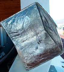 The reflector can be made from any suitable material. Some do-it-himselfers get good results even with reflectors made of cardboard covered with aluminum foil. In this case, keep in mind that the connector must have good contact with the inside of the reflector. To reduce windage, a solid reflector can be replaced with a grid with a cell side, which can be calculated in our online calculator. The lengths of the active and passive elements are measured from the surface of the reflector, and the distances b and c are measured from the surface of the reflector to the center of the corresponding pin. The dimensions of the reflector are optimal, further increase in the size of the 3D-angle does not make sense, since it does not lead to an increase in gain. Simply removing the passive element increases the input impedance to 72 ohms, allowing the antenna to be used with a 75 ohm feeder.
Related links:




The site has comments on social networks, which have much more opportunities for communication.