


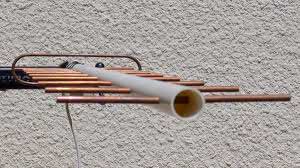
 A few years back, video blogger KREOSAN generated massive hype around his "Wi-Fi gun." Many people concluded that all it took was a marker, pliers, and scissors to slap together any microwave antenna without much effort or understanding. They'd then post it on their video blog, hoping it might go viral and turn a profit. What's worse, even failed attempts riddled with glaring technical errors get uploaded to video hosting platforms, leading inexperienced viewers to draw similarly flawed conclusions. In this article, we'll break down these mistakes using one of the most popular antennas as an example: the Yagi-Uda. We'll examine a design for the 2400 MHz Wi-Fi band and analyze how seemingly minor assembly details—ones that appear insignificant at first glance—can cause the antenna to perform abysmally or fail completely.
1) Building any antenna starts with calculations, and it's crucial to get them right. We have a separate article dedicated to this topic. It's worth noting that, unlike most microwave antennas, free software like MMANA-GAL and 4NEC2 can be used to calculate Wi-Fi Yagi-Uda designs. Most radio amateurs involved in antenna building use at least one of these tools. But not video bloggers! They take the easy route and often find our online DL6WU Yagi-Uda calculator through a web search, using it as their only resource. This is the first mistake. A Wi-Fi antenna built using dimensions from this calculator will not work properly. Why? The calculation algorithm was developed almost 50 years ago to simplify antenna construction for amateur radio bands. This is evident from the ham radio call sign in the design's name. This Yagi design offers stable gain and a consistent radiation pattern when arbitrarily adding directors. However, its input impedance is far from ideal. Radio amateurs easily solve this problem using a hairpin match or gamma match with manual "by-instrument" tuning. The calculator can also be used to create a "rough" antenna model for subsequent optimization in 4NEC2, but using its calculation results directly to build a Wi-Fi antenna is completely unacceptable. "Why do you publish such 'unsuitable' calculators then?" an anonymous commenter might ask. And we'd reply: "This isn't what you think—you need to understand the deeper layers here."
So, we've concluded that electromagnetic simulators are essential for calculating microwave antennas—there's no way around it. Calculators can only be used as a preliminary calculation tool. As an example, we'll take a 16-element Yagi-Uda design for Wi-Fi calculated in 4NEC2. To build the antenna, you'll need a piece of solid copper wire with a diameter of Ø2.05 mm (12AWG) and a rigid PVC tube conforming to the American standard 1/4" Schedule-40, with an inner diameter of 9.3 mm and a wall thickness of 2.2 mm. Ø2 mm holes are drilled in the tube, into which the copper elements are tightly inserted. The antenna uses a folded dipole made from the same wire. It's bent and trimmed to size after the wire has been inserted into the tube. The antenna dimensions, including element lengths and positions relative to the reflector, are compiled in the table.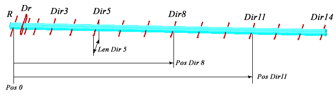
| Elements | Len | Pos |
|---|---|---|
| R | 62 | 0 |
| Dr | 58 | 19 |
| Dir1 | 48 | 25 |
| Dir2 | 48 | 42 |
| Dir3 | 48 | 73 |
| Dir4 | 48 | 111 |
| Dir5 | 48 | 155 |
| Dir6 | 47 | 202 |
| Dir7 | 47 | 250 |
| Dir8 | 47 | 300 |
| Dir9 | 46 | 350 |
| Dir10 | 46 | 400 |
| Dir11 | 46 | 448 |
| Dir12 | 45 | 495 |
| Dir13 | 45 | 540 |
| Dir14 | 44 | 581 |
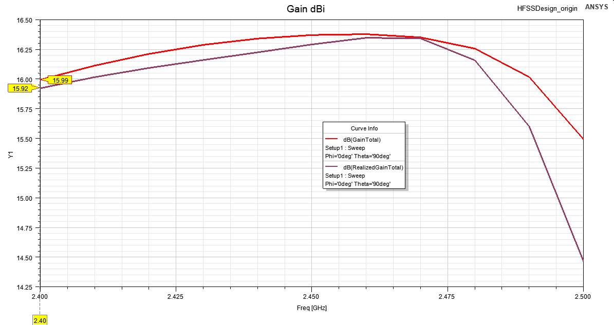
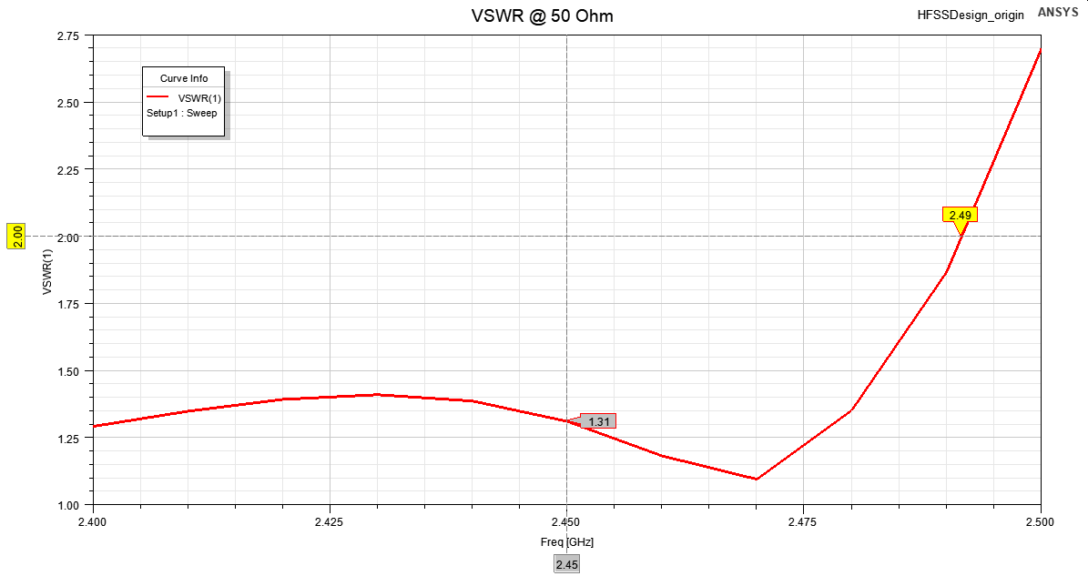
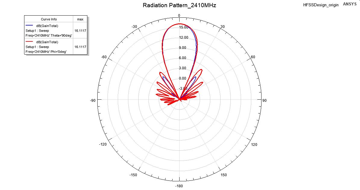
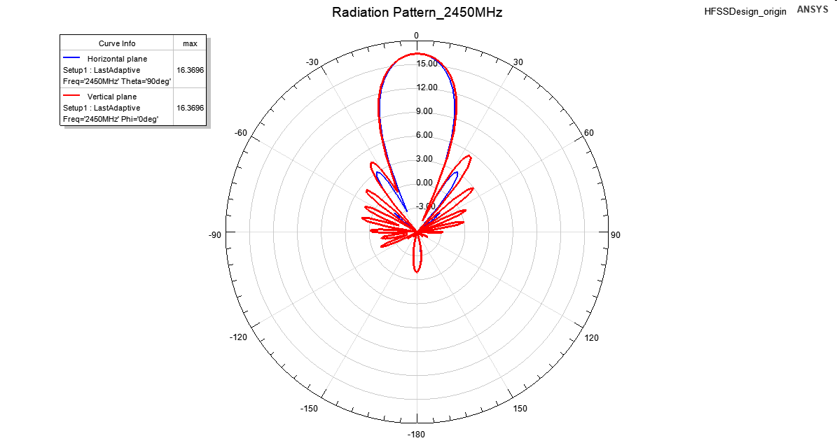
The calculated antenna gain is 16 dBi, with VSWR not exceeding 1.75 across the operating band. The antenna characteristics are shown below. Comparing these characteristics with the original 4NEC2 model calculation results, one might conclude that the dielectric boom has no effect on the antenna's parameters. As will be shown below, this is not the case. At microwave frequencies, the influence of the dielectric boom must be taken into account, as it causes element shortening compared to calculations in 4NEC2 or MMANA-GAL.
 |
 |
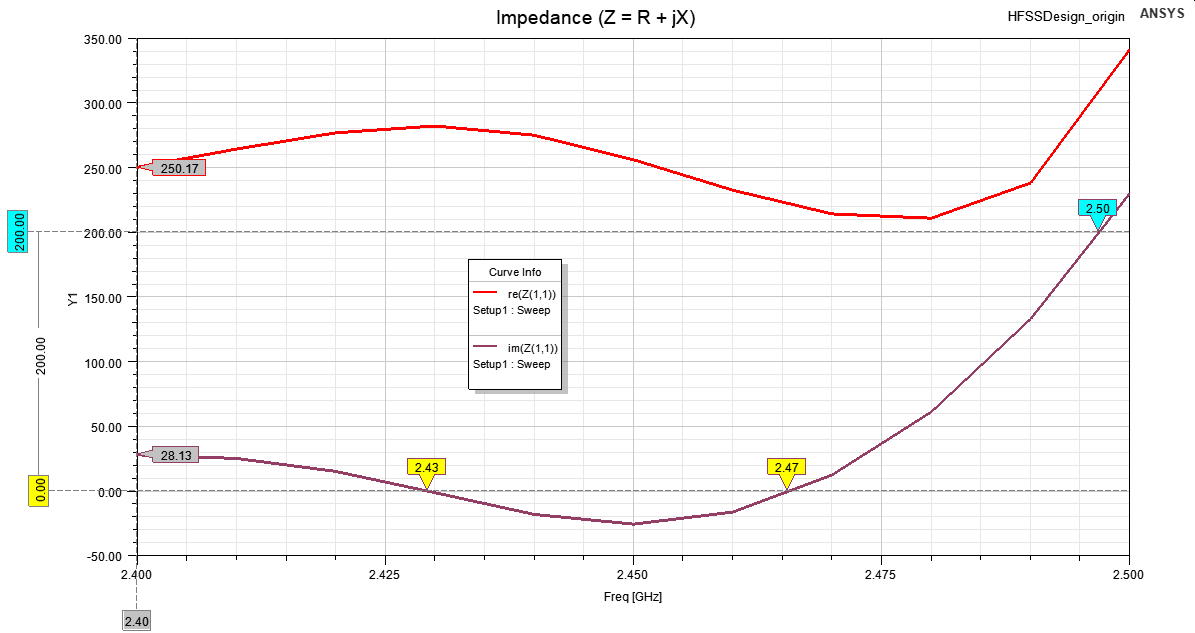 |
| Gain | VSWR | Impedance |
 |
 |
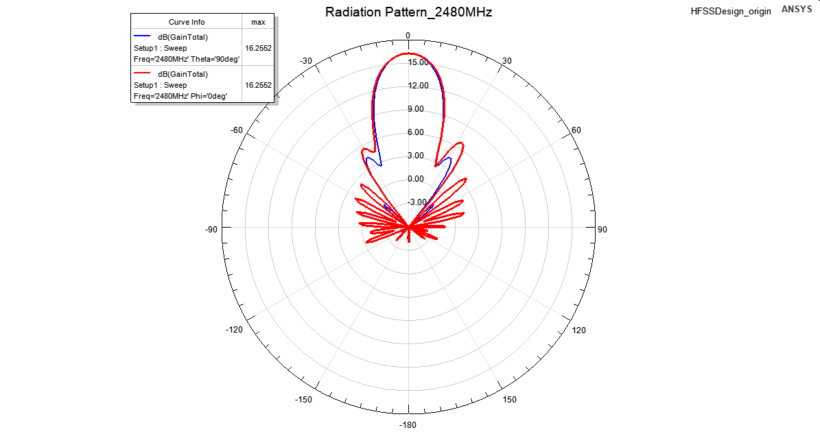 |
| Radiation pattern at 2410 MHz | Radiation pattern at 2450 MHz | Radiation pattern at 2480 MHz |
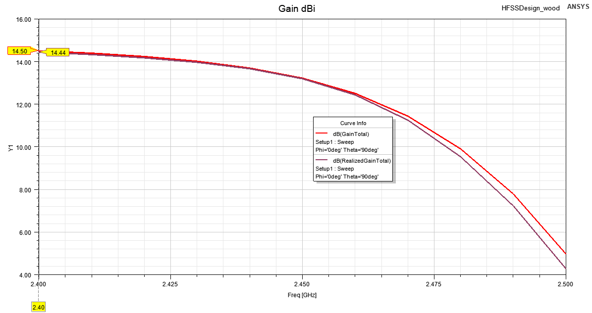
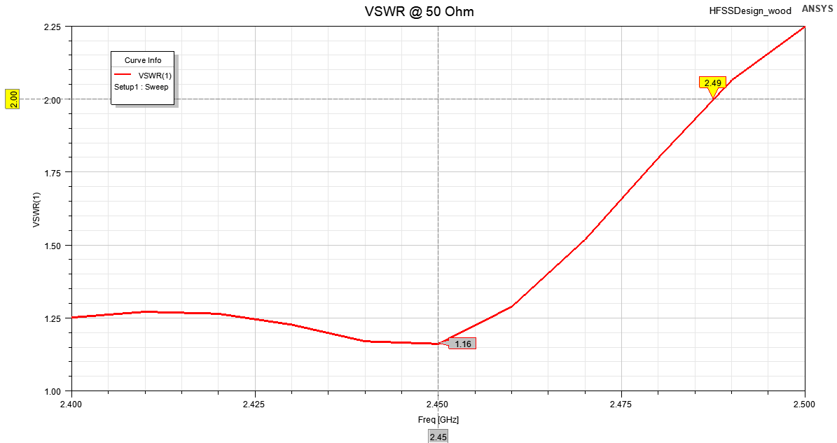
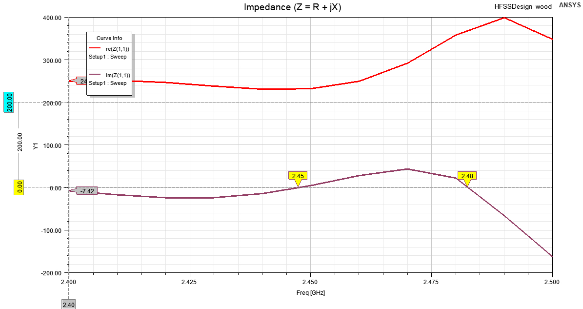
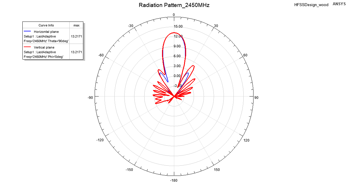
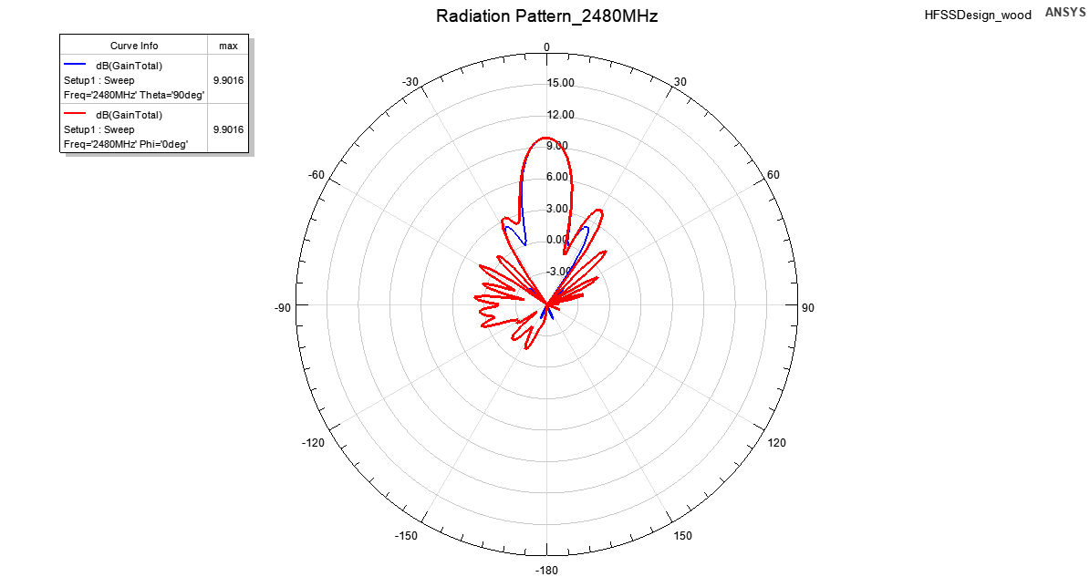
2) Errors Related to Deviations from the Base Design. Video bloggers quite often mount Yagi-Uda elements on a wooden boom. It's commonly believed that a dielectric/wooden boom has no significant effect on the antenna's parameters. This may hold true at VHF or UHF frequencies, but it's no longer the case at microwave frequencies. Below are the characteristics of the same antenna on a pine boom with a cross-section of 20×15 mm:
 |
 |
 |
| Gain | VSWR | Impedance |
 |
 |
 |
| Radiation pattern at 2410 MHz | Radiation pattern at 2450 MHz | Radiation pattern at 2480 MHz |
As we can see, the antenna characteristics have changed. Gain has dropped significantly, especially on the higher Wi-Fi channels. Antenna efficiency has decreased from 99% to 56%. If all element lengths are shortened by 2 mm, the antenna characteristics become more uniform across the band; however, efficiency does not exceed 75%, which is considered very poor. Furthermore, wooden beams tend to absorb moisture, causing the antenna characteristics to deteriorate even further.
The second issue is that it's not always possible to find materials with the required dimensions and cross-sections. Just try finding a tube conforming to American standards or wire with the exact diameter needed. Let's take more readily available materials: a tube with an outer diameter of 16 mm and a wall thickness of about 3 mm, and solid copper wire from electrical wiring with a cross-section of 4 mm² (Ø2.3 mm). The antenna characteristics will drift again, and to retune the antenna, all elements will need to be shortened by 1 mm. The good news is that antenna efficiency no longer drops as it did with the wooden boom. As we can see, any seemingly insignificant deviation from the original antenna design can lead to degraded performance and requires separate recalculation of element dimensions.
3) Errors Related to the Pigtail and Balun Connection Point. This is a very sensitive part of the antenna. However, it's precisely here that the greatest number of errors occur, which can lead to complete antenna failure. Two such cases are shown in the image below.
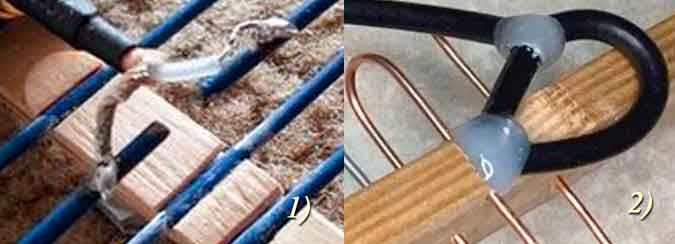 In the first part of the image, the pigtail is connected with long leads and without a balun. This is completely unacceptable. The pigtail and balun leads must be minimal and should not exceed 1-2 mm at these frequencies.
 The second part also contains several errors. First, the wrong balun is used. The image shows a 3λ/4+λ/4 balun, whereas a folded dipole requires a λ/2 balun—a half-wave loop. Second, the connection point, the antenna's feedpoint, is filled with hot glue. This has a very negative impact on antenna characteristics, to the point of radiation pattern distortion and efficiency dropping below 50%. The pigtail and half-wave loop are best connected with short leads to the ends of the folded dipole, as done in the Amos antenna. The spacing between the folded dipole ends should also be minimal. A connector to which the balun shield is soldered can be used. For the pigtail and balun, it's better to use coaxial cables with heat-resistant insulation that doesn't melt during soldering, rather than RG58. For example: RG178, RG316.
Using the Wi-Fi band Yagi-Uda as an example, we've examined the main errors that can lead to failure when building antennas for the microwave range. This doesn't even account for the fact that the Yagi is quite a finicky antenna and highly sensitive to manufacturing inaccuracies. In our site's terminology, it has poor repeatability. For this reason, we don't recommend the Yagi as a DIY antenna for Wi-Fi/4G—at least not for radio amateurs who don't have an antenna analyzer at their disposal. A better option would be any design based on a patch antenna that doesn't require a balun, such as the aforementioned "gun," or for Wi-Fi, a panel antenna like this one.




The site has comments on social networks, which have much more opportunities for communication.