


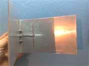
 The corner reflector antenna was invented by American radio amateur & radio engineer John Kraus (W8JK) in 1938 and patented in 1940. This is not his only invention in the field of antennas, it is enough to mention another of his creations — a helical antenna, to appreciate his talent as an inventor. The antenna has a very simple design: a reflector bent in the form of an angle and a dipole placed along the bisector of this angle. Despite its simplicity, the antenna has quite good characteristics and can be recommended as an outdoor 4G or Wi-Fi antenna.
 The use of a corner reflector antenna in the Wi-Fi range was proposed by Dragoslav Dobričić (YU1AW), the inventor of the Amos antenna. To balance the antenna, he proposed to use a split coaxial balun. However, he later removed the description of this design from his website. This is due to the fact that the 3D-corner antenna (volumetric corner reflector) is more efficient and easier to make with less material expense. However, a split coaxial balun in combination with a dipole significantly expands the bandwidth of the antenna system as a whole. We analyzed this mechanism in detail in the description of BiQuad broadband antenna for two bands. For this reason, in our opinion, this design should not be abandoned, since it is quite suitable not only for Wi-Fi, but also for any 4G band. Such an antenna allows scaling and its design dimensions can be calculated using an online calculator.
The online calculator for this antenna is based on the ANSYS HFSS computer model, which can be downloaded from this link. The calculated antenna gain is about 13 dBi, the input impedance is 50 ohms. SWR within the operating range is not more than two, the suppression of the back lobe of the radiation pattern is not worse than 30dB. Reflector opening angle 70°.
Schematic images of the antenna (click on the one you need to enlarge):
 |
 |
 |
| 3D view | Side view | Bottom view of the radiating element and the balun |
JavaScript source code:
Copyright ©2016 - 3G-Aerial
Limitations and features of antenna calculations
The entire antenna, reflector, dipole, and balun are made of sheet metal, for example, galvanized steel with a thickness of 0.2 ... 0.5 mm. A reflector made of a whole piece of tin with a width of rW and a length of rB + 2*rH. The dipole and balun can also be made from a single piece of metal, bent as seen in the third image of the antenna schematic, and attached to the reflector using the connector nut. The hot strip of the balun, which is soldered to the center conductor of the connector, can be made from a strip of copper or brass and attached to the vibrator with a rivet.
The characteristics of the antenna for the LTE1-2100MHz and LTE3-1800MHz bands are shown below (click on the desired image to enlarge):
 |
 |
 |
| Input impedance | VSWR | Gain dBi |
 |
 |
 |
| Input impedance | VSWR | Gain dBi |
The radiation pattern in all bands is almost identical:
The theory and other design options for an antenna with a corner reflector are described in more detail in the ARRL Antenna Book 21st Edition, p.18-14 (Chapter 18)
Related links:
- The Square-Corner Reflector Beam Antenna for Ultra High Frequencies. BY JOHN D. KRAUS,* W8JK - ARRL (PDF);
- John D. Kraus Memorial Amateur Radio Club (W8JK) - NAAPO
- https://sikandarhyat.wordpress.com - design of Sikandar Hunzai;


The site has comments on social networks, which have much more opportunities for communication.