


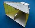
 The calculator computes the so-called optimal pyramidal horn antenna. The smaller the opening angle (the greater the length of the horn at a constant aperture), the smaller the phase errors at the edges of the aperture, the narrower the major lobe, and the greater the horn antenna gain. However, this significantly increases the consumption of material and the cost of the antenna. With a large opening angle, the antenna is more compact, but the resulting phase errors lead to the fragmentation of the antenna pattern major lobe and a decrease in the gain. To solve this problem, one resort to technical solutions in the form of curving fins, as in the figure. However, it is rather problematic to implement this solution in radio-amateur conditions. An easier way is to choose a certain optimal opening angle at which phase errors are considered acceptable.
The calculations are based on the following assumptions:
- The optimal aperture sizes ratio (Ap/Bp) for a pyramidal horn is 3:2;
- Standard side ratio (a/b) of rectangular waveguide is 2:1;
- Cross-sectional dimensions of a rectangular waveguide a and b selected from the condition of propagation in it only waves of the main mode H10;
The main article on the design of the antenna is here.
The pin of the coaxial-waveguide transition of height h is soldered to the central terminal of the connector, which is located exactly in the center of the waveguide wide side at a distance l1 from the rear closing wall of the waveguide and at a distance l2 from the mouth of the horn.
Schematic representation of the antenna:

Javascript source code:
Copyright ©2015 - 3G-Aerial
Limitations and features of antenna calculations
Schematic representation of the cutting of the waveguide and antenna:

To verify the calculator, some sample antenna options were simulated in the ANSYS HFSS simulator. The calculation results are summarized in the table below (click on the desired image to enlarge):
 |
 |
 |
 |
| Input impedance | VSWR | Gain | Radiation pattern |
 |
 |
 |
 |
| Input impedance | VSWR | Gain | Radiation pattern |
 |
 |
 |
 |
| Input impedance | VSWR | Gain | Radiation pattern |
 |
 |
 |
 |
| Input impedance | VSWR | Gain | Radiation pattern |
 |
 |
 |
 |
| Input impedance | VSWR | Gain | Radiation pattern |
To use waveguides of standard sizes, more accurate calculation in the electromagnetic simulator is required.
Related links:
- Introduction to Horn Antennas;
- Horn antenna - Wikipedia;


The site has comments on social networks, which have much more opportunities for communication.