


 We bring to your attention, dear anonymous, BiQuad antenna, optimized for digital television. Of course, it is equally suitable for both analog and digital television of any standard, which is broadcasting in the UHF range. Why do we position it as a "digital" antenna? Firstly, very little time will pass, and we will think of analog TV as some kind of antique, like a gramophone. And about the "secondly" should be told in more detail. Original BiQuad antenna consists of two square loops with a perimeter of about 1λ, connected in parallel. Such an antenna has a low input impedance of about 75 ohms, which is very convenient for direct connecting with a 75 ohm feeder without impedance transformer, and for balancing it is usually enough to pass this cable along one of the arms of the square loop. BiQuad 50 ohm antenna is also great for amateur bands 144/433/1296 MHz, for GSM-900, GSM-1800, WiFi-2400. If you need a simple antenna without an amplifier with an input impedance of 75 ohms for one TV multiplex, then you can use the original version of the BiQuad antenna, which you can calculate by our online calculator. Here we offer an improved high-performance version of the BiQuad antenna, which can work in conjunction with an outdoor antenna amplifier and is able to overlap almost the entire TV UHF range.
Currently, different countries have allocated different, but fairly wide frequency bands for digital television. At the same time, digital multiplexes are often scattered over the entire range, and relatively narrowband antennas are of little use in this case. To cover a wide range, you can use other versions of the BiQuad antenna, which have a higher input impedance. For example, rhombus double loops with a perimeter of one of the loops of about 1.5λ have an input impedance of about 300 ohms, which makes the antenna more broadband and easy to match with 300/75 ohm baluns or antenna amplifiers, that are currently widely represented on the market. Just such an antenna was developed by a user under the nickname yurik82 through digital optimization in NEC2 and subsequent verification in the ANSIS HFSS program (details at the end of the article). You can download archive with 4NEC2 and HFSS models for detailed study.
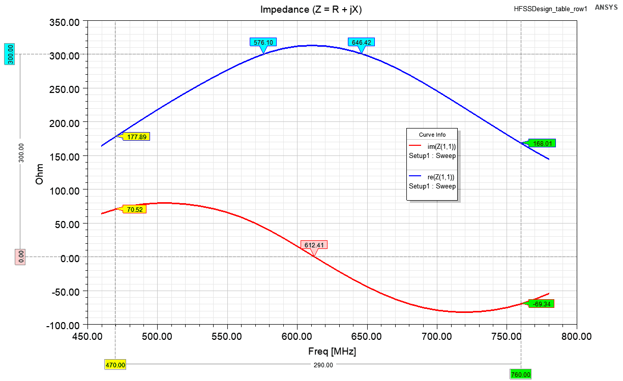
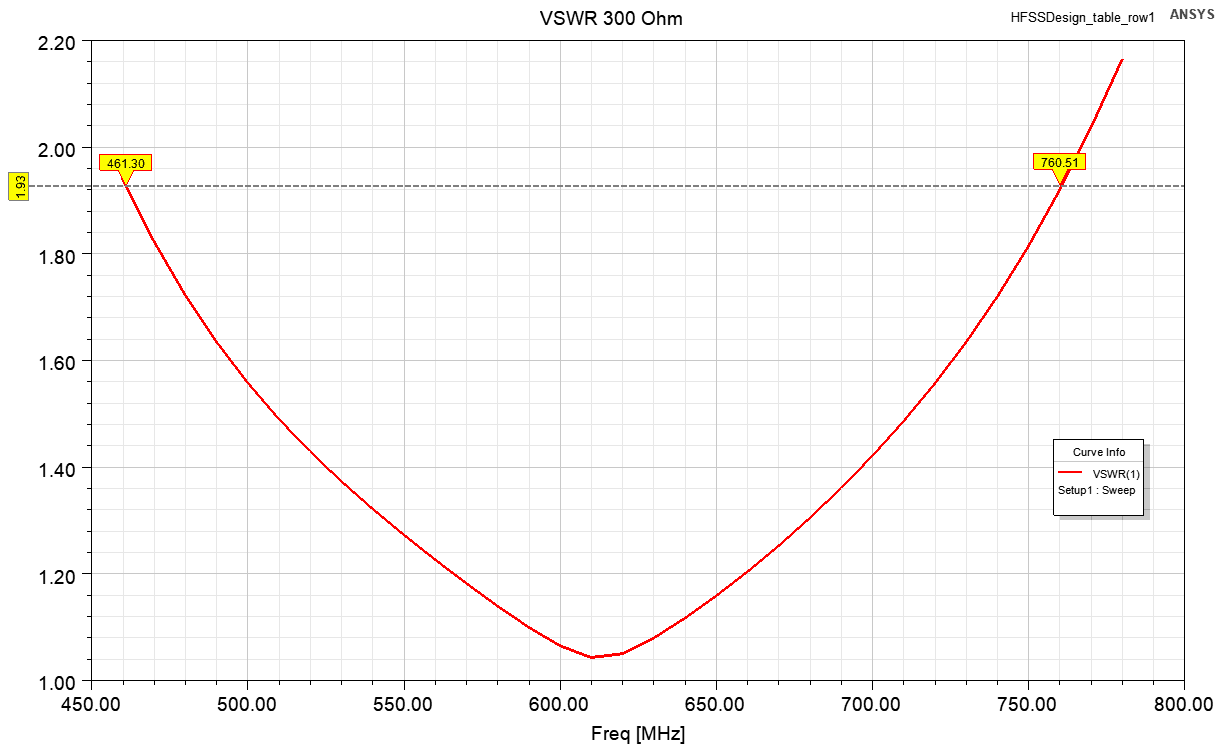
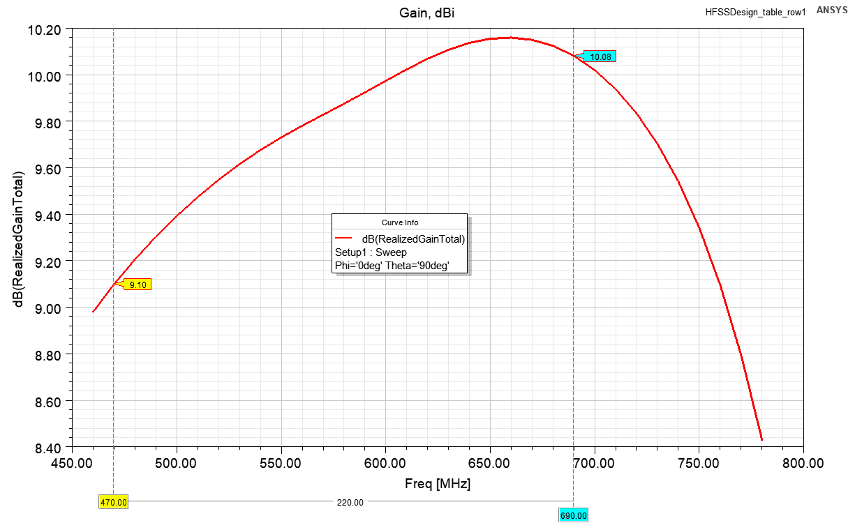
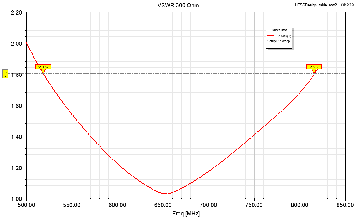
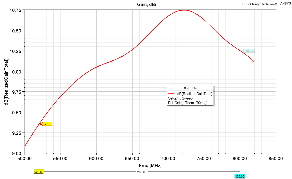
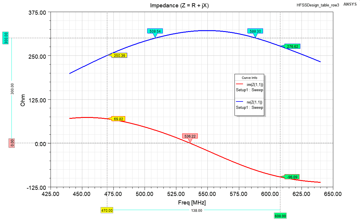
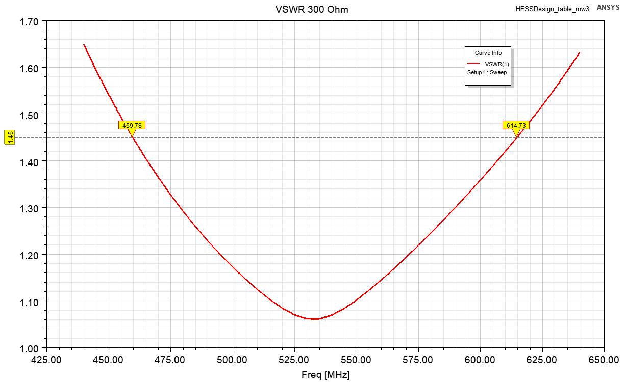
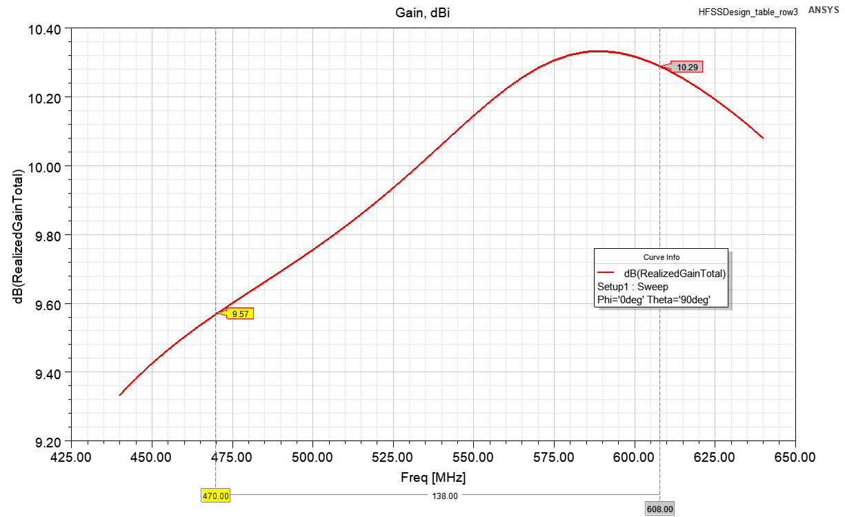
The result is a simple antenna with an input impedance of 300 ohms, a gain of 9.5 ± 0.5 dBi and a bandwidth of 470-760 MHz according to the SWR < 2 criteria. The antenna is easy to make, has very good repeatability, does not require tuning and can be made by yourself from the most available materials. In comparison with the classical BiQuad antenna, this option has the following features:
- much wider operating band with comparable gain;
- possibility of direct connection to N and M points of plate baluns or SWA/PAE/ALN amplifiers;
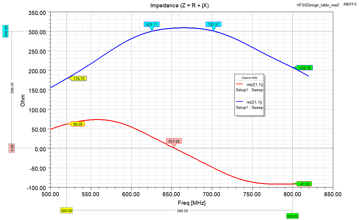
Unfortunately, such an antenna does not cover the full range of 470-860 MHz, therefore, if in the region where the anonymous lives, some multiplexes operate at frequencies above 750 MHz, it is advisable to recalculate the antenna upward, reducing all dimensions by 10%, sacrificing gain on the lower channels. This version of the antenna size is indicated in the second row of the dimensions table. The antenna is completely symmetrical both along the vertical and horizontal axes passing through the center of the antenna. Therefore S=EF=CD, R=CE=DF, AC=AD=BE=BF, CN=DM=EN=FM. All dimensions are from the center to the center of the wire, i.e. along the axes of the wires. The distance to the reflector is measured from the plane on which the axes of the wires of the loops are located to the surface of the reflector. The dimensions (along the axis of the wire):
| f MHz | W | H | R | S | T | G | Offset | AC | CN |
|---|---|---|---|---|---|---|---|---|---|
| 470…760 | 400 | 500 | 308 | 262 | 476 | 20…60 | 148 | 156 | 192 |
| 520…800 | 400 | 500 | 277 | 236 | 428 | 20…60 | 133 | 140 | 172 |
| 470…608 | 450 | 550 | 338 | 288 | 521 | 20…60 | 163 | 171 | 213 |
In comparison with famous designs, this version of the BiQuad antenna has undeniable advantages, such as broadband with comparable gain, uncritical dimensional accuracy, and ease of making.
With a reflector size of 40x50 cm, the aperture efficiency reaches 130% at the lower channels, i.e. for such a gain, this is a quite compact antenna and its dimensions are fully justified by the obtained gain. The width of the major lobe of the radiation pattern is about 70°. As a radiating element, you can use a common copper or aluminum electrical wire 4 mm2 (#12 AWG) or 10 mm2 (#8 AWG), with a margin of 1.5 meters (5 ft) of wire is enough. A thicker conductor is preferred due to hardness and added load capacity. You can use other improvised materials - galvanized or brass tapes. As a reflector, you can use a building galvanized mesh with cells of 20x20 or 20x50 mm. If the antenna is hidden from the wind (for example, in the attic floor, balcony, close to the facade), the reflector can be made of solid galvanized tin sheet. It is desirable to mount the tops of the BiQuad (points A and B) on metal racks/bolts, then the radiator will be connected to the reflector by DC, which contributes to the flow of static charges to the grounded mast, and not to the balun and further to the television cable and to TV set. Antenna parameters do not differ for a grounded BiQuad and for an isolated one. Because galvanized mesh does not have hardness and load-bearing capacity; to maintain its shape, it is necessary to make 2 horizontal crossbars (from a duralumin corner or strip) at the level of the tops of the BiQuad. Attach the radiator mounting bolts to these horizontal struts. The technological gap G in the center can vary within small limits depending on the box used, in which the 4:1 balun (the simplest such balun is the half-wave coaxial balun) or antenna amplifier of the SWA/PAE ALN type will be hidden.
The main characteristics of the antenna, calculated in the ANSYS HFSS program, can be seen in the images below. Click image to enlarge.
 |
 |
 |
| Input impedance | VSWR | Gain |
 |
 |
 |
| Input impedance | VSWR | Gain |
 |
 |
 |
| Input impedance | VSWR | Gain |
P.S: Information useful for antenna design specialists from yurik82:
- BiQuad with a fixed loop perimeter with full symmetry of the double loop has 4 main degrees of freedom:
- distance from the center of symmetry to the vertex A(B);
- distance from the center to the CD(EF) line;
- the length of this line;
- distance from the loops to the reflector;
- In order to choose these sizes in an optimal way (to maximize the gain with SWR < 2 limitation), a Python script developed by N.Mladenov for the NEC2 engine was used:
https://github.com/nikiml/nec.opt
Using non-linear programming methods, such a script automatically goes through tens of thousands of combinations of "antenna degrees of freedom". The result is an antenna model in which the desired properties are maximized.
The end result was also tested in the ANSYS HFSS simulator (results in 4NEC2 and HFSS are exactly the same)
https://ypylypenko.livejournal.com/20678.html
Related links:
- 4NEC2 models of different Bi-Quad antenna variants - Initial antenna prototypes for this article's design;




Simply use your calculator for 539Mhz? (the center of the new band) Or are there other things to be considered in making a broad-band antenna for ch14-36?
I have a material I like with holes 38mm x 135mm and some fence not at strong with holes 50mm x 100mm.
Do 38mm x 135mm openings make a good reflector?
Or, should I look further?
Thanks, Mikek
3g-aerial.biz/en/online-calculations/other-calculations/metal-grid-antenna-reflector-online-calculator
The cells of 38×135 give a loss of about 0.15 dB. This is quite an acceptable loss.
Thanks, Mike
www.anodas.lt/en/antenna-amplifier-swa-2000-4t
Currently, shielded amplifiers with a built-in filter against unwanted interference are being manufactured:
www.dipolnet.com/box_antenna_amplifier_lna177-5g_27_db_with_lte_5g_filter_shielded_B4009.htm
Unfortunately, I couldn't find such amplifiers on Amazon. So, you should find another variant. Besides, it seems to me that the possible supply of such amplifiers or relative antennas could be a profitable option for business.
The Biquad I built matchs the low SWR frequency of your graph at about 530MHz,
but the other frequencies don't do as well. I'm not sure if it is my antenna, my measurement or what. I did have Grok convert these numbers because I measured a 75Ω antenna on a 50Ω system.
480MHz 2.0
500MHz 1.667
520MHz 1.466
530MHz 1.051
540MHz 1.167
560MHz 2
580MHz 2.467
600MHz 1.533
620MHz 1.367
Is your graph of SWR theoretical or measured?
Thanks, Mikek
Ah, I just looked at the design and gathered parts to build a Coaxial current balun last night, I'll soon swap my transformer for the Coaxial current balun and retest.
Thank, Mikek
Tanks, Mikek
There's no optimal distance. They must be placed at a distance no less than the maximum antenna size. Furthermore, two antennas can't simply be connected "in parallel." Impedance and phase matching must be maintained.
There are simple dual biquad designs, such as these:
imageevent.com/holl_ands/multidiamond