


 The "Double ellipse-rectangle" brought to your attention is one of the few professional designs that can be safely recommended for DIY makers who don't have special devices for tuning antennas. The antenna is a modification of the “elliptical patch” known in the professional community. Why patches are especially popular at the microwave frequencies and why the elliptical patch is good, we have analyzed in sufficient detail in the Ellipse Patch 2x2 antenna article, so we will not repeat it. However, often a radio amateur is stopped by the need to cut a proper ellipse out of metal sheet. Try to make a proper circle, not to speak of an ellipse! The design presented here, while keeping all the advantages of the “Ellipse Patch”, allows you to make it “rectangular” without cutting crooked lines.
On the one hand, the patch looks like a straightened ellipse, on the other — like a rectangle with cut corners. The result is the "Ellipse-rectangle". From two such patches, interconnected by a wired unbalanced transmission line, a phased antenna array is assembled. The antenna has a gain of more than 14 dBi, input impedance 50 ohms, SWR does not exceed 1.7. As an example, the characteristics of the antenna for the DCS-1800 band are given: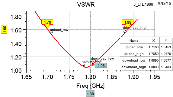
 The antenna is calculated in the ANSYS HFSS simulator for most 3G/4G bands. The project file with a set of models can be downloaded from our website. We do not provide an antenna calculator here. The antenna has many non-scalable dimensions and the calculator in this case is simply inappropriate. All dimensions are summarized in the table below. The symbols are clear from the drawings:
 The reflector is bent in the form of a U-shaped box with dimensions W, H and D, that is slightly opening in the form of a horn. The patches are located symmetrically with respect to the reflector center at a distance S between the centers of attachment. They are fastened with bolts passed through a metal pipe with a diameter of Dof and a height Of
 The patches are connected to a wired phasing line using trapezoid tabs with T1, T2, T3 dimensions. The tabs can be cut from one piece of metal along with the patch. The wire of the phasing line with dw diameter, connecting the patches to each other, is located at a height h above the reflector. The same distance h from the lower part of the tab to the reflector. The thickness of the metal for patches is about 1 mm at frequencies below 1 GHz, 0.5...0.8 mm in the 1800 & 2100 MHz bands and 0.3...0.5 mm for LTE-2600. The thickness of the metal for the reflector is selected based on the criterion of mechanical strength, not less than 1 mm. In 3G/4G networks, vertical polarization is used, and the antenna should be positioned as in the first figure — vertically. To implement MIMO technology, it will be necessary to make two separate such antennas. They should be located at an angle of 90° to each other, but not horizontally/vertically, and according to the conditions of the so-called X-polarization, at an angle of 45° to the horizon (see photo below). Why so, detailed in the article about MIMO technology.
 The center conductor of the input connector is connected to the T2 side of one of the tabs at the phasing TL end. You can exclude the connector and pass the feeder through the reflector using the modified male F-connector. A hole for the connector is drilled in the reflector opposite one of the tabs. The central conductor is connected to the tab at the same point where the phasing line is connected.
| Size | Band [MHz] | ||||
|---|---|---|---|---|---|
| 800 | 900 | 1800 | 2100 | 2600 | |
| A | 236 | 210 | 109 | 96 | 75 |
| B | 172 | 153 | 80 | 70 | 55 |
| C1 | 71 | 63 | 33 | 29 | 22 |
| C2 | 40 | 31 | 19 | 17 | 13 |
| S | 368 | 328 | 170 | 150 | 117 |
| D | 196 | 175 | 90 | 80 | 62 |
| H | 733 | 689 | 357 | 316 | 246 |
| W | 550 | 490 | 254 | 225 | 175 |
| L | 135 | 120 | 62 | 55 | 43 |
| Of | 34 | 31 | 15 | 14 | 11 |
| Dof | 8 | 8 | 6 | 6 | 6 |
| T1 | 42 | 36 | 21 | 20 | 15 |
| T2 | 7 | 5 | 5 | 5 | 4 |
| T3 | 32 | 29 | 13 | 12 | 9.5 |
| h | 2 | 2 | 2 | 2 | 1.5 |
| dw | 2.25 (4 mm²) | 2.25 (4 mm²) | 2.25 (4 mm²) | 2.25 (4 mm²) | 1.78 (2.5 mm²) |
 If we compare this antenna with the popular “Yagi-disk”, it has twice the gain. TWICE! It needs much less “iron”. Again, you should cut the metal in straight lines, which is much simpler. No need to worry about circles/ellipses, it lets to easier keep dimensional accuracy...
We add compressed photos of the finished MIMO antenna. Click on image to enlarge. An archive with full-grown photos with a resolution of 20 Megapixels can be downloaded from Google disk.
 |
 |
 |
 |
 |
 |
 |
 |
Related links:


1. Is the patch electrically connected to the reflector? From the way it is mounted with the bolt, it seems that way
2. Are the reflectors connected together with the metal profile used for mounting? Doesn't this turn it into one big antenna (making MIMO not work)?
I don't know anything about antenna design, so I'd like to make sure I build it right.
The thing is that direct current and high-frequency currents flow through metal in completely different ways. We have an article on our website “About RF transmission lines” in which we tried to describe this phenomenon.
Therefore, electrical short connection of the antenna parts relative to DC does not affect its operation on high frequency. Moreover, it is necessary to protect the equipment from atmospheric static electricity and to correctly switch the modem from the internal antenna to the external one.
No. This antenna is only for 2100 MHz band.
3g-aerial.biz/en/choice-of-material-for-the-antenna
Usually, galvanized steel is used (steel covered by zinc) as the most practical and low-cost option. You can see just this material on the photos above.
The material of the screws/bolts and nuts is not critical. It is only necessary that they are metal, that is, provide a DC short circuit of the patches and the reflector.
It is not a coaxial cable. It is a solid copper wire.